What are Voltage Dividers?
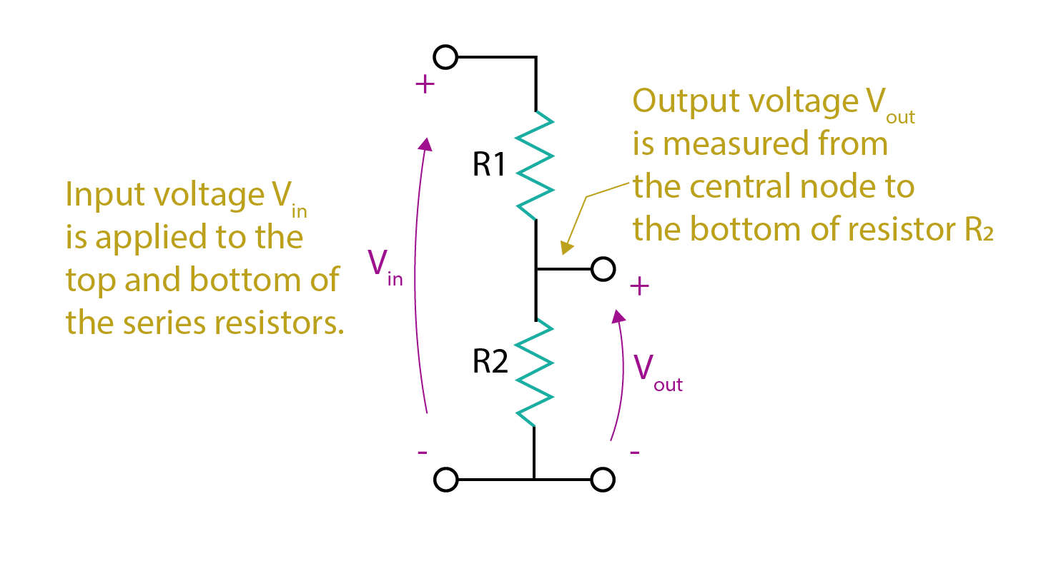
Voltage divider circuits work by producing different voltages from a single voltage source. This is mainly a resistive circuit, but capacitive and inductive voltage dividers are also used as and when required. There can be any n number of elements in it.
It is a series circuit where current remains constant, and voltage is divided among the elements in a series circuit. Voltage divider circuits can also provide negative constant voltages by inverting terminals concerning supply and ground.
Voltage Dividers Equation
Given below is the voltage divider equation that can be used to calculate the voltage across a resistor. As the formula shows, the resistance across which voltage is to be calculated is taken in the numerator and the total resistance of the branch is taken in the denominator multiplied by the total voltage provided by the source.
Potentiometers as Voltage Dividers
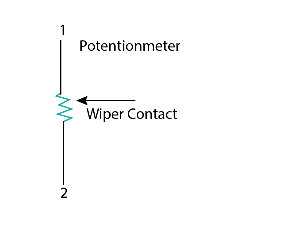
Potentiometer is the most commonly used voltage divider. It consists of a resistor and a sliding contact. The sliding contact moves to change the value of the resistor. This is done manually by the user. The sliding contact is also known as the wiper contact.
It is represented by an arrowhead symbol, as shown in the diagram. When the wiper contacts move towards point 1 resistance decreases and as the wiper contact moves to point 2 resistance increases. At point 2 resistance is maximum.
Types of Voltage Division Circuits
Voltage division circuits are classified based on elements used in them such as resistors, capacitors, inductors, etc. The types of voltage divider circuits described below are:
1. Resistive Voltage Dividers
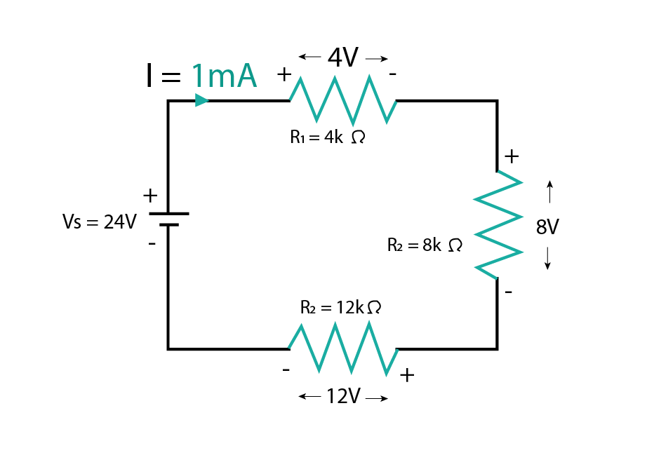
Calculate the voltage across each resistor in the given circuit.
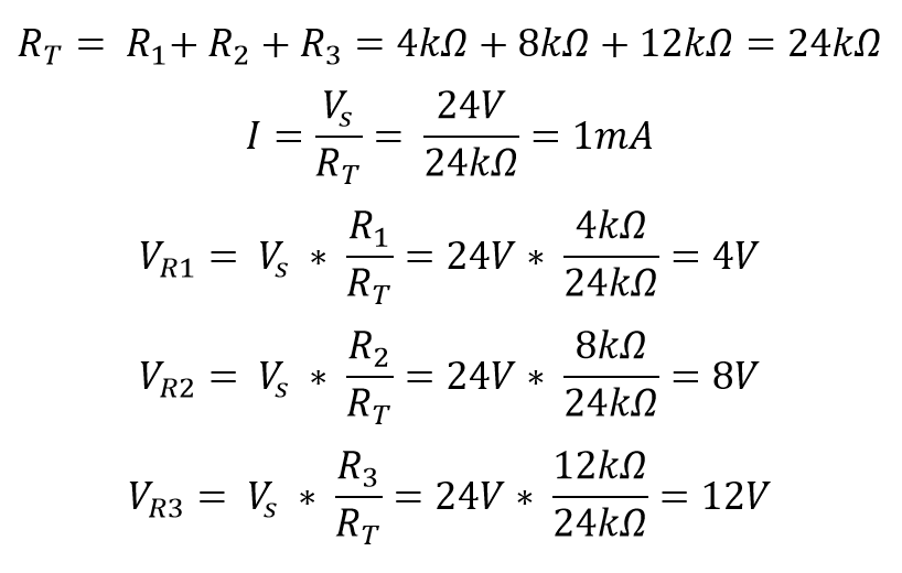
The given circuit is a series resistive circuit with three resistors in series with a voltage source of 24V. The values of resistances are given as R1 = 4KΩ, R2 = 8KΩ, and R3 = 12KΩ. We need to calculate the voltage that is dropped across each resistor.
If we add up VR1, VR2, and VR3 then we again get 24V as an answer that also proves Kirchhoff’s voltage law.
2. Capacitive Voltage Dividers
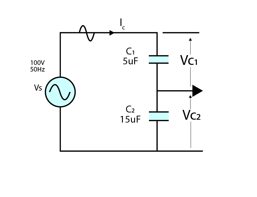
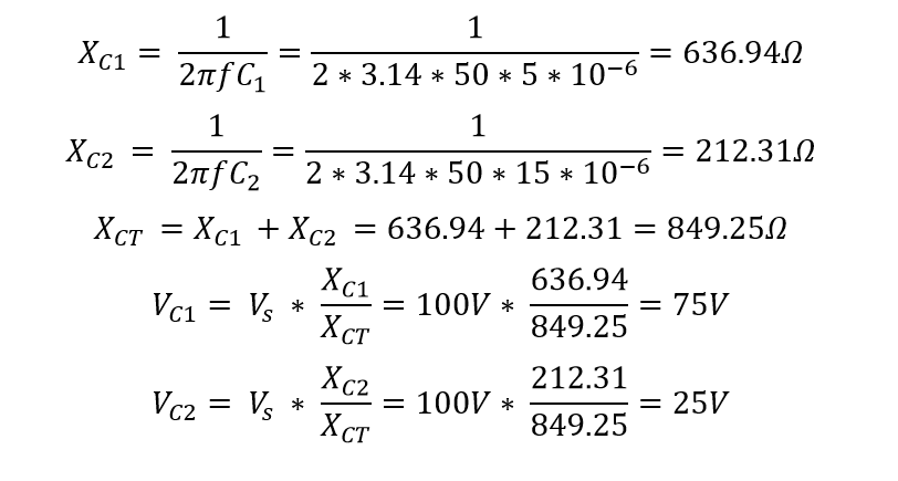
The given circuit is a series capacitive circuit with two capacitors in series with a voltage source of 150V. The values of capacitance are given as C1 = 5uF and C2 = 15uF. We need to calculate the voltage consumed across each capacitor. For this purpose, I will first have to calculate the reactance of the capacitors.
If we add up VC1 and VC2 then we again get 100V as an answer that also proves Kirchhoff’s voltage law.
3. Inductive Voltage Dividers
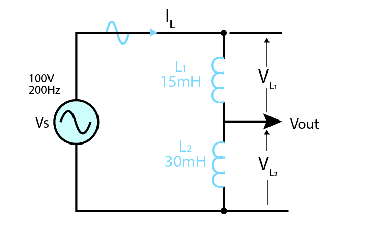
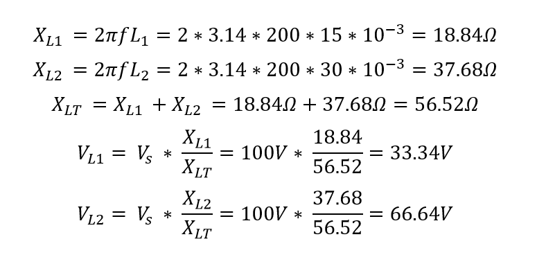
The given circuit is a series inductive circuit with two inductors in series with a voltage source of 100V. The values of inductances are given as L1 = 15mH and L2 = 30mH. We need to calculate the voltage across each inductor. For this purpose, I will first have to calculate the reactance (XL) of the inductors.
Kirchhoff’s voltage law is not directly applicable to inductive voltage divider circuits. It is because inductors produce magnetic fields inherently. Therefore, it can be solved by taking the integral of inductor voltages.
Conclusion
A voltage divider is a series circuit with a single voltage supply that is divided among the elements of the circuit connected in series. The VDR voltage divider rule allows us to calculate the voltage consumed across each element or component of the circuit. It is used in multimeters, Wheatstone bridge, and for adjusting the level of signals and supply voltage where required.

