What is Monostable Multivibrator
These multivibrators have two operational states; a stable state and a meta-stable state. Stable states are permanent while quasi-stable states occur only temporarily during their operation. When one side of the transistor conducts, the other side is left in a state where it does not conduct. A transistor is said to be in a stable condition when it is in a state that does not allow it to change unless it is triggered by an external trigger pulse.
Construction of Monostable Multivibrator
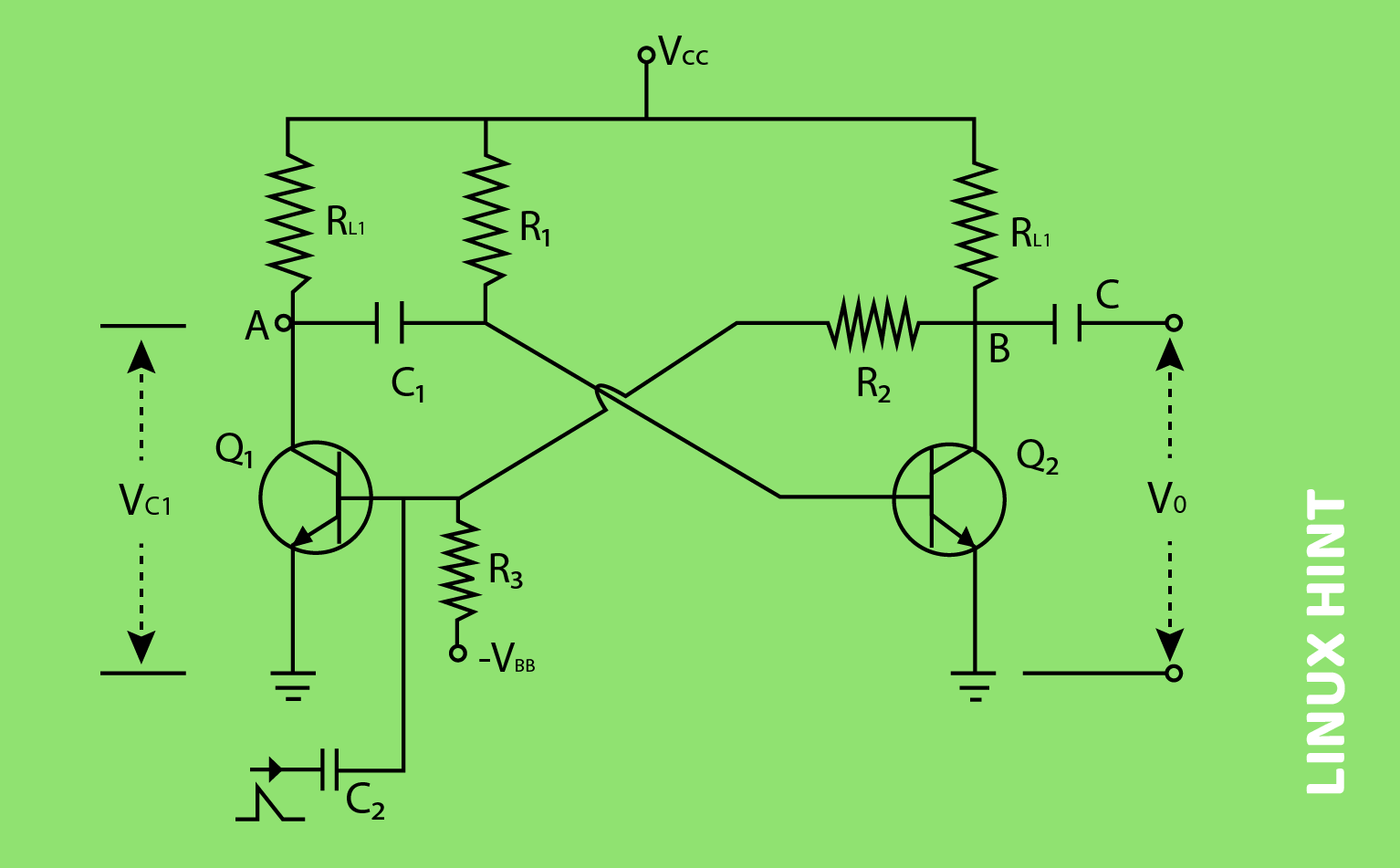
A feedback circuit in these multivibrator circuits is provided by two transistors, Q1 and Q2, which are coupled to one another. Through capacitor C1, the collector of the initial transistor denoted as Q1 is linked to the base of the next transistor denoted as Q2, which completes the circuit. Through the capacitor C and resistor R2, the base Q1 of the initial transistor is linked to the collector of the next transistor Q2. Another DC supply voltage, shown by the symbol -VBB, is delivered through resistor R3 to the base of transistor Q1. The base of Q1 receives the trigger pulse, which causes it to transition into a different state, via the capacitor C2. Load resistors Q1 and Q2 are denoted by RL1 and RL2, respectively.
When one of the transistors reaches a condition in which it is stable, an external trigger pulse is applied to change the state of the transistor. After switching its states, the transistor will remain in a meta-stable state for a certain amount of time. The length of this time is specified by the values of the RC time constants, after which it will return to its prior stable state.
Working Principle of Monostable Multivibrator
When the power is first applied to the circuit, the transistor Q1 will be switched to the OFF state, while the transistor Q2 will be switched to the ON state. This represents a state of stability. Since Q1 is not conducting, the collector voltage at point A will equal VCC; hence, C1 will be charged. When a positive trigger pulse is supplied to the base of the transistor Q1, it causes the transistor to go into its ON state. This causes the collector voltage to drop, which ultimately results in the transistor Q2 being turned off.
At this point, the capacitor C1 begins its process of discharging. When the positive voltage from the collector of the second transistor Q2 is applied to the first transistor Q1, it stays in the ON state even though it was initially turned off. This state is referred to as the quasi-stable state.
The OFF state is maintained by the transistor Q2 until the capacitor C1 has been discharged in its entirety. After this, the voltage that is being delivered by the capacitor discharge causes the transistor Q2 to flip ON, turning on the device. This causes the transistor Q1, which was in a stable state before, to become active.
Output Waveform Representation
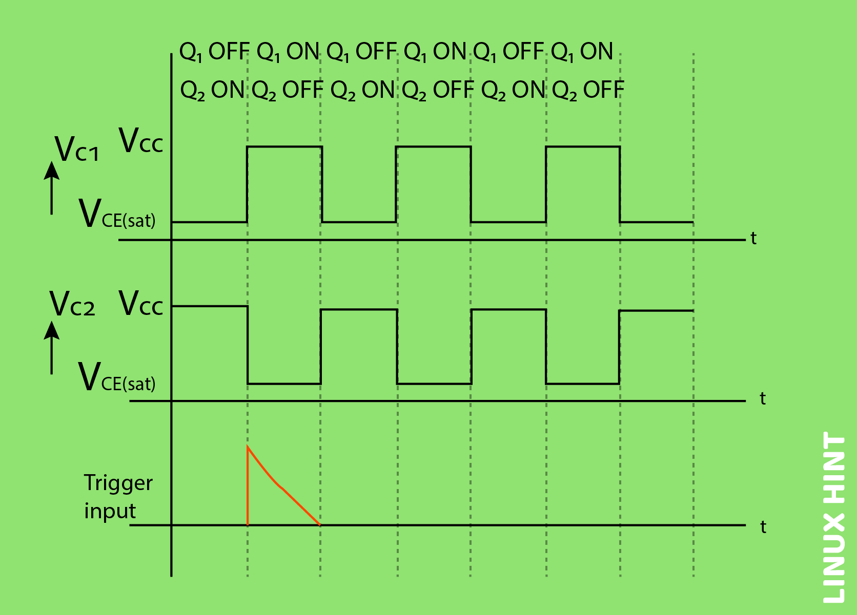
The voltage waveforms at the output for collectors of the first transistor Q1 and second transistor Q2 as well as the trigger input that was delivered at the base of the first transistor Q1 are shown below:
The length of this output pulse is determined by the RC time constant that is being used. As a result, it relies on the product of R1C1. The length of the pulse can be determined by:
The input for the trigger will be present for a very short period, and its sole purpose will be to start the operation only. This causes the circuit to transition from its stable state to a condition that is either Quasi-stable, Meta-stable, or Semi-stable, and the circuit will remain in this state for a relatively short period. Each time there is a trigger pulse, there will be a corresponding output pulse.
Conclusion
The monostable multivibrators have applications in a variety of applications, including television circuits and control system circuits, amongst others. They have very simple circuit designs as well as less expensive construction components.


