A filter or frequency filter is a type of circuit that filters selective frequency signals but allows all other frequencies to pass through it. This article describes high pass filter, working principles, frequency and phase graphs along with examples.
High Pass Filter
A high pass filter is a resistor-capacitor based circuit that passes a signal above cutoff frequency while blocking all other frequencies below it. The arrangement of resistor and capacitor in the circuit is exactly opposite to the low pass filter as shown below:
Working Principle
At low frequencies, the reactance of the capacitor is quite high, and it behaves like an open switch in the circuit. The capacitor keeps on blocking all lower frequencies until the frequencies reach a specific cut-off value of the frequency fc. As the frequency rises above the cut-off frequency, the capacitor drops its reactance significantly to act like a short circuit, allowing all the frequencies to reach the output.
Therefore, the high pass filter blocks all lower frequencies below the cutoff frequency, while allowing all other frequencies above the cut-off value.
Frequency Response Representation
The frequency response curve for a high pass filter representing the output voltage and phase shift is presented below:
The output remains negligible until the cut-off frequency point is attained. The output rises here to +20db/Decade. The phase shift representation depicts a phase shift of +90 degrees between output and input and lower frequencies until the phase shift becomes +45 degrees at the resonant frequency point.
The pass band of the high pass filter shows constant output till indefinite higher frequencies. However, in practice, the high pass filter does not pass infinite frequencies but remains within limits due to limitations of electronic components.
Cut-Off Frequency, Phase Shift & Voltage Gain
The cut-off frequency is expressed as:
The phase shift is expressed as:
The circuit gain, AV is:
Since frequency and reactance are inversely proportional, at low frequencies, XC high values up to infinity; Vout is zero. Whereas, at high frequencies, XC reaches minimum values almost equal to zero, resulting in Vout equals to Vin .
Second Order High Pass Filter
The RC network is replicated and connected to provide the second-order high-pass filter. If a single pass filter has a slope at 20 dB/decade, the cascaded second-order high pass filter will have a slope of 40 dB/decade.
The cut-off frequency can be expressed in terms of two resistors and capacitors as mentioned below:
Example
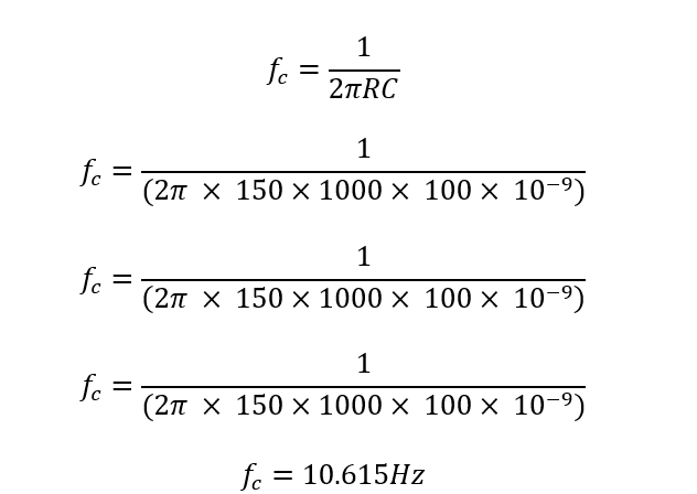
If a 100nf capacitor with 150 kΩ resistor, then find out the cut-off frequency of the high pass filter.
As previously established, the high pass filter’s cut-off frequency is determined by:
Conclusion
All frequencies below the cut-off frequency value fc, are blocked by a high pass filter. The cut-off frequency is considered at 70.7% or -3dB of the voltage gain value. The corresponding output signal at this cut-off frequency is +45 degrees.


