- What is Voltage Regulation
- Voltage Regulation of a Transformer Under Load
- Voltage Regulation for Leading Power Factor
- Voltage Regulation for Lagging Power Factor
- Example 1
- Example 2
- Conclusion
What is Voltage Regulation
Voltage regulation is a term associated with measuring the difference in voltage between the sending and the receiving end. Voltage regulation defines how well the electrical component or device can hold the voltage constant in varying load conditions. In the case of transformers, voltage regulation gives the percentage of voltage loss.
Voltage Regulation of a Transformer Under Load
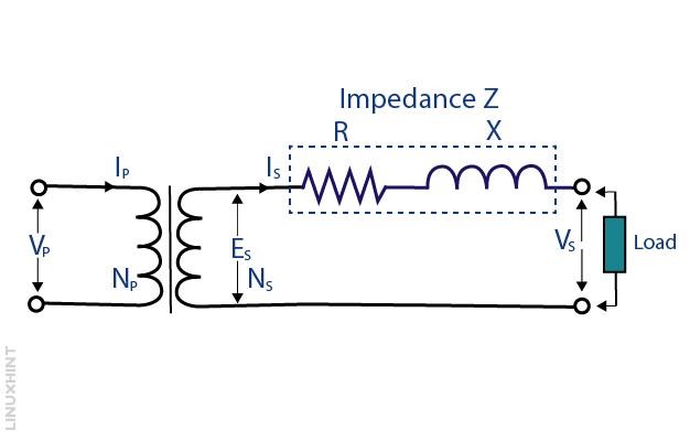
There are primarily two types of voltages, one that is in no load condition (VNo-load) and the other is in the load conditions (Vfull-load). When there is no load connected to the secondary side of the transformer, there is no load current and the transformer is open-circuited, thus acting as a single winding having a higher self-inductance.
However, when the load is connected to the secondary side, the current starts to flow at a certain power factor from the internal winding of the transformer. There are some variations in the secondary voltage because of the load variation and the internal resistance of the transformer. So here is the mathematical expression for calculating the voltage regulation of a transformer:
The voltage regulation mainly depends on the power factor, and it can be either leading or lagging. When the current is leading the voltage, it would be leading, which mostly happens in the capacitive circuits. However, when the voltage is leading the current the power factor is said to be lagging, which mostly happens in the inductive circuits. So, as a result, the voltage regulation differs when the power factor is lagging or leading.
Voltage Regulation for Leading Power Factor
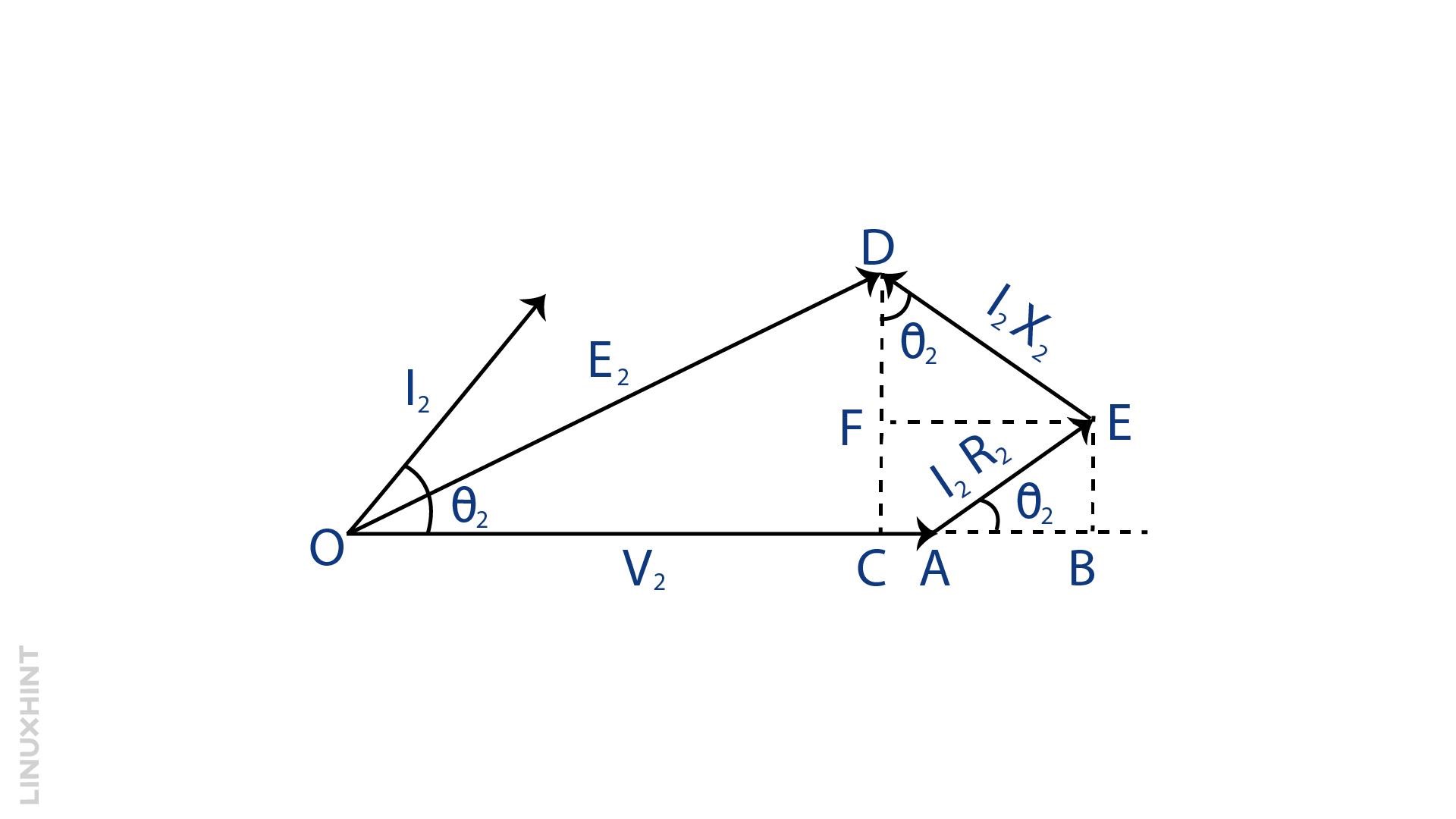
As mentioned above, the leading power factor is the one when the current is leading the voltage so to derive the formula for the leading power factor consider θ2 the angle between the current and the voltage, so the leading power factor of load will be cosθ2, below is the phaser diagram of a transformer having a leading power factor:
Here,
Since the angle between OC and OD is negligible in that case, consider the same angle for both, so:
Now just put the values for the E2 – V2 in the voltage regulation formula as given below:
Voltage Regulation for Lagging Power Factor
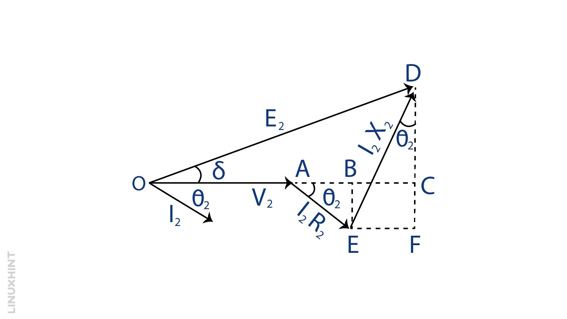
The power factor is said as lagging if the current lags the voltage by a certain angle and mostly the inductive circuits have a lagging power factor so to derive the voltage regulation formula consider the θ2 as an angle between the secondary voltage and current. The lagging power factor will be cosθ2 and below is the transformer phaser diagram having a lagging power factor:
Here,
Since the angle between OC and OD is negligible in that case, consider the same angle for both, so:
Now just put the values for the E2 – V2 in the voltage regulation formula as given below:
Example 1: Calculating Voltage Regulation of transformer with lagging Power Factor
There is a 10 KVA transformer which provides the secondary voltage under no load conditions of 110 volts. The resistance of the secondary winding of the transformer is 0.1 Ohms, then the reactance is approximately 0.5 Ohms and the power factor when the load is connected is 0.85 lagging, find the voltage regulation:
First, find the angle by taking the inverse of the cosine and then calculate the sine of that angle:
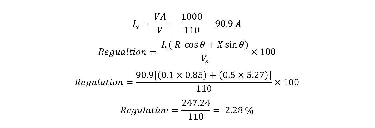
Now calculate the secondary current and put the values in the voltage regulation formula for the lagging power factor:
Here, the voltage regulation is 2.28 which depicts a variation of 2.28 % between the sending and receiving sides.
Example 2: Calculating Voltage Regulation of transformer with leading Power Factor
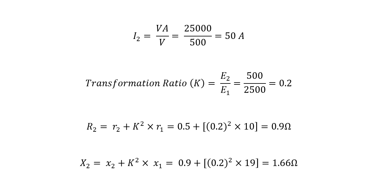
A 25 KVA step-down transformer that receives a voltage of 2500 volts and is stepping down to 500 volts has resistance for the high voltage winding of 10 ohms and an inductance of 19 ohms. The resistance is 0.5 Ohms, and the inductance is 0.9 Ohms for low-voltage winding, find the voltage regulation with a 0.8 leading power factor.
Finding the current on the secondary winding and the respective resistance values:
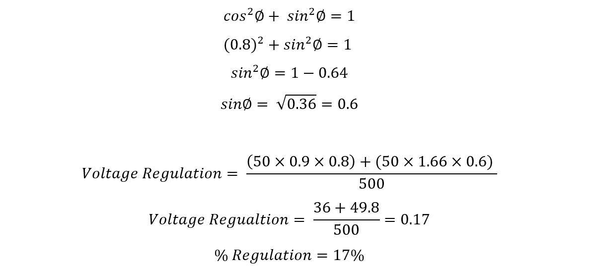
Now finding the voltage regulation for the transformer having a leading power factor, for calculating the sin() value using the following trigonometric formula:
Conclusion
Voltage regulation is the measurement of how much voltage loss occurs when going from one end to another. Moreover, it also depicts how well the device, or the circuit component can hold the voltage. In the case of a transformer, the voltage regulation should be between 3-5 %.

