For the transmission and distribution of electricity, alternating current and voltage is used, and one of the main reasons for that is that it can be easily generated and transformed to higher or lower levels. Generally, the voltage is transformed to higher levels before transmitting because at long distances there are considerably higher line losses. The transformation of voltage and current is carried out by transformers, keeping the power of the system the same. Transformers usually have two states when it is under load and when no load is connected to it that is no load condition.
Outline:
- Transformers Under Load
- Transformer On-load Phasor diagrams
- Transformer on Load Phasor diagrams Based on its Internal Impedance
- Having No Winding Resistance and No Leakage Reactance
- Having Winding Resistance and Leakage Reactance
- Transformer Phasor diagrams Based on its Load
- Example 1
- Example 2
- Example 3
- Conclusion
Transformers Under Load
When the load is connected across the secondary side of the transformer, the current starts to flow from the load coming from the secondary winding. This current is the result of the induction of the secondary voltage generated due to the magnetic field produced by the flow of current through the primary winding.
The current in the secondary winding is determined by the characteristics of the load, and it produces a self-induced magnetic field whose direction is opposite to the magnetic field on the primary side. The opposition of these two magnetic fields results in the combined magnetic field that has a lower strength as compared to the magnetic field generated in the transformer by the primary side under no load conditions.
The Back EMF of the primary winding is reduced due to the combined magnetic field and as a result, the primary current tends to increase by a small amount. This primary current will continue to increase until the magnetic field is back at its original strength, and that’s why a balanced condition should exist between the primary and the secondary magnetic fields of the transformer. The balance between the transformer’s magnetic field will result in the balance of the power, which ultimately keeps the transformer working correctly. Below is a basic transformer circuit with which the load is connected:
The induced voltage of the transformer can be found from the turn ratio of the transformer, as it is proportional to the number of turns in that winding. Moreover, the power input and output of the transformer are the same so:
So now the ratio for voltage and current of the transformer will be:
Now, the relationship between the ratio of turns of the transformer can be written as:
It is to be noted that the current has an inverse relationship with the number of turns and voltage. So, when the secondary side of the transformer is loaded to keep the balance between the sides, if the voltage is stepped in then the current should be lowered or stepped down. The total current in the primary winding from the supply is the sum of the no-load current and the current from the secondary side. The phasor diagram is shown below if the current lags the voltage by a phase angle ϕ:
Transformer On-load Phasor Diagrams
In ideal conditions, the transformer windings have no leakage reactance and winding resistance, but practically there is some leakage reactance and winding resistance. So, while drawing and studying the phasor diagrams for the transformer, they should be taken into consideration. The internal impedance of the transformer is mainly due to the resistance of the windings and the drop in the inductance, which is also known as leakage reactance. This leakage reactance results in flux leakage, causing a voltage drop in the transformer, below is the transformer circuit that displays its internal impedance:
To make the calculation easy and simpler, the internal impedance can be combined and displayed at a corner in the diagram:
The transformer phasor diagram varies based on the load conditions and the internal impedance of the transformer. So, there are different phasor diagrams based on internal resistance and load characteristics.
Transformer on Load Phasor diagrams Based on its Internal Impedance
The internal impedance of a transformer greatly affects its working, as it has the tendency to increase the chances of certain losses like core losses and copper losses. Based on the internal impedance of the transformer, below are some conditions for the phasor diagrams:
- Having No Winding Resistance and No Leakage Reactance
- Having Winding Resistance and Leakage Reactance
Having No Winding Resistance and No Leakage Reactance
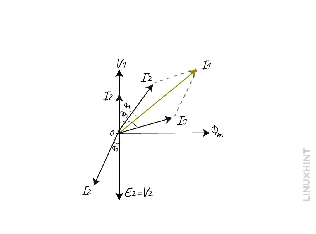
This is normally the ideal case when the transformer has no leakage current and winding resistance. The flow of current starts through the secondary winding which then goes to the load when the load is connected, below is the transformer phasor diagram under load considering no internal impedance:
As mentioned above, the current primarily depends on both the secondary voltage and the type of load. This current is named the secondary current and is denoted by I2. Due to this flow of current a magneto motive force will be generated in the secondary winding which results in procuring the flux ϕ2. This flux opposes the magnetizing flux of the primary winding, reducing the self-induced EMF E1.
When the E1 falls below the level of primary voltage V1 then the extra current starts to flow from the source to the primary winding. This additional current I2′ will produce an extra flux of angle ϕ’ which will be minus the effect of the secondary flux. In such a way, the flux of the core will remain constant despite load characteristics.
The current now can be divided into two parts, one is used for compensating the core losses of the transformer, and the other is used to compensate for the flux of the secondary winding.
Having Winding Resistance and Leakage Reactance
Practically, the transformer always has some winding resistance and leakage flux, in that case the voltage equations for the primary and secondary windings will be:
Now to further simplify the equations we get:
The equation for the total impedance of secondary and primary winding is:
So now the equations for voltages will be:
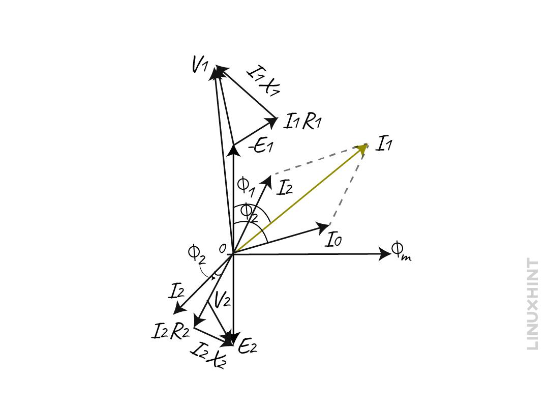
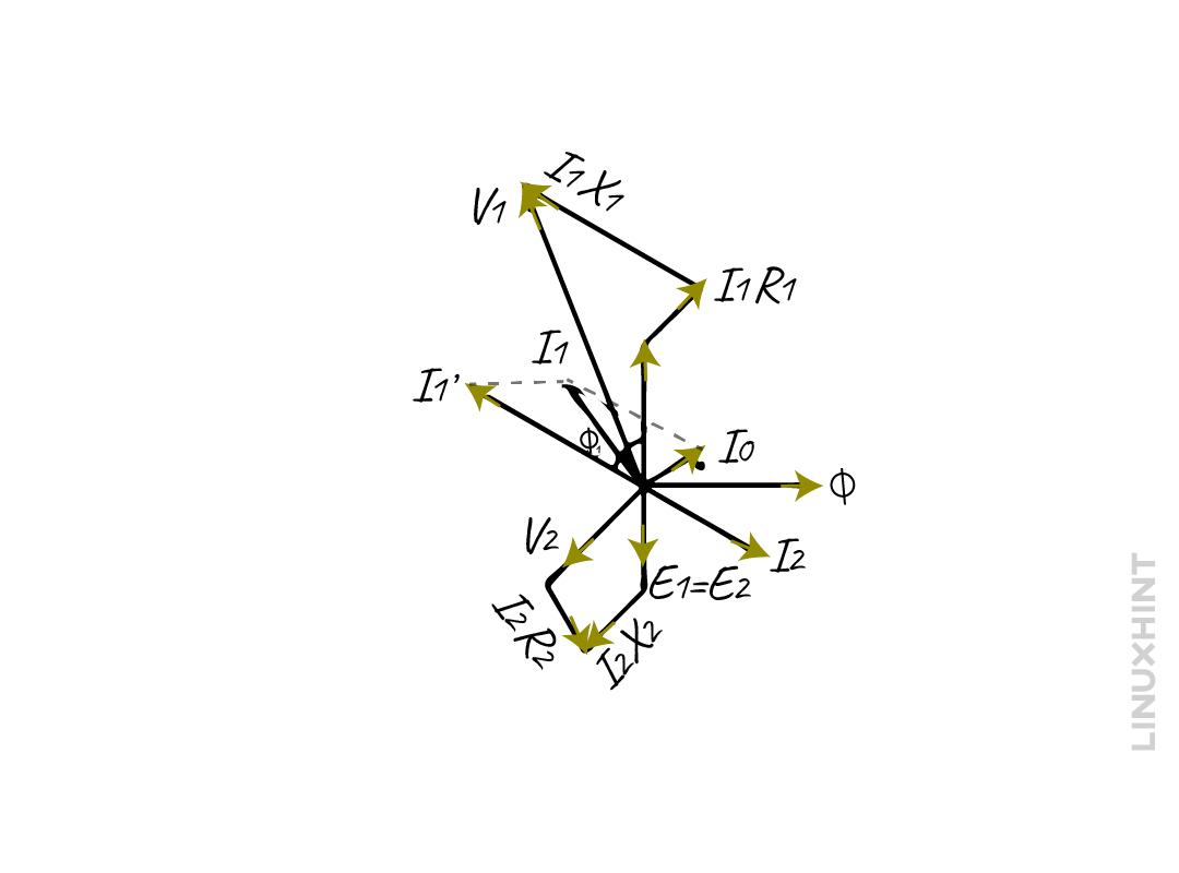
In this case, the EMF E1 is less than the primary voltage due to the internal impedance of the transformer. Moreover, due to a voltage drop in the secondary winding resistance R1 and leakage reactance X2 the secondary voltage is less than its induced EMF E2. The phaser diagram for the transformer on load with winding resistance and leakage flux is:
Here the EMF E1 and E2 lag the flux ϕm by the angle of 90 degrees and the current I’2 is the compensating current that counters the secondary current I2. The I0 is the on-load current of the transformer thus the total current will be the summation of both the no-load current and the compensating current:
Transformer Phasor Diagrams Based on its Load
Generally, there are three types of loads in AC circuits which are: resistive, inductive and capacitive and transformer behave differently for each type of load. So, depending on the load type there would be three different phasor diagrams for the transformer:
- Resistive Load
- Inductive Load
- Capacitive Load
Resistive Load
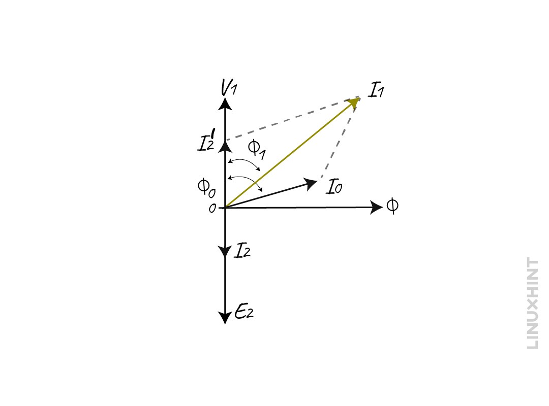
When the resistive load is connected to the transformer, there would be no phase shift because the voltage and current are in phase. This is because the resistor neither store energy nor releases any energy. Moreover, the voltage regulation for the transformer will be quite less. The power factor for the resistive load will be leading and near to unity as there are no reactive components, below is the phasor diagram of a transformer with resistive load.
Here V1 is the primary voltage and I1 is the primary current whereas I2 is the secondary current and E2 is the secondary voltage. The secondary current denoted by I2 and the secondary voltage denoted by E2 are in phase, so the angle is zero. Similarly, the ϕ1 is the phase difference between the primary current and voltage and ϕ0 is the phase difference between the no-load current and voltage.
Inductive Load
When an inductive load is applied across the secondary side of the transformer, the current starts to flow through the load from the secondary winding. The current lags the voltage by a phase difference of 90 degrees, and thus the induced EMF E1 and E2 lag the flux by the phase difference of 90 degrees. The power factor becomes lagging and more current is drawn from the supply to counter the extra secondary flux.
The internal impedance of the transformer causes the voltage drop, so the voltage on the secondary terminal is the phase difference between the voltage drop and E2 which can be written as:
The current I2 is in phase with the V2 whereas the I2X2 and the current I2 are out of phase with 90 degrees. So, the total current I1 from the above phasor diagram can be written as:
The equation for the primary voltage can be written as:
Now the relationship of the current I1 with V1, and I1X1 is the same as mentioned above and the ϕ1 is the phase difference between the Current I1 and the voltage V1.
Capacitive Load
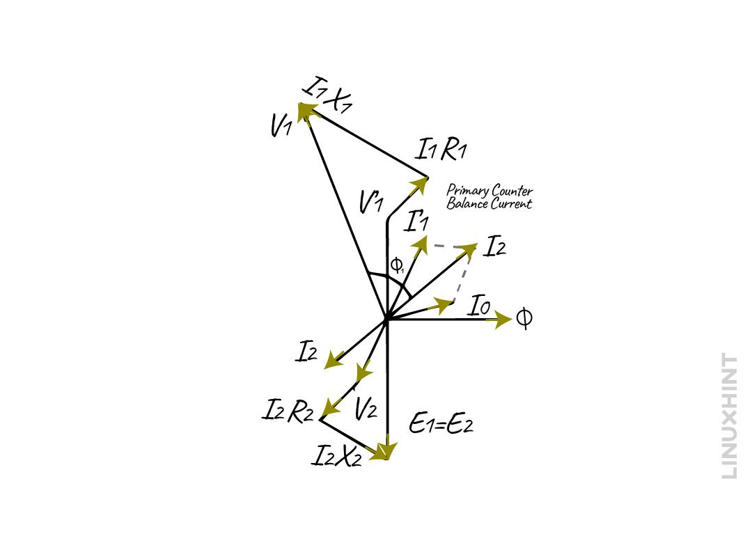
The only difference between the inductive load and the capacitive load is that the current leads the voltage by 90 degrees and the power factor for the capacitive load is always leading. Here in the phasor diagram below it can be seen that the current is leading the voltage by an angle of ϕ1:
The internal impedance of the transformer causes the voltage drop, so the voltage on the secondary terminal is the phase difference between the voltage drop and E2 which can be written as:
The current I2 is in phase with the V2 whereas the I2X2 and the current I2 are out of phase with 90 degrees. So, the total current I1 from the above phasor diagram can be written as:
The equation for the primary voltage can be written as:
Now the relationship of the current I1 with V1, and I1X1 is the same as mentioned above and the ϕ1 is the phase difference between the Current I1 and the voltage V1.
Example 1: Calculating Primary Current for Transformer Loading
Consider a single-phase transformer having a current of 1 Amp on the primary with a power factor of 0.4 lagging under no load condition. The number of primary turns is double that of the secondary. If the load is connected to the transformer and draws a current of 50 Amps with 0.8 lagging power factor, then find the current in the primary winding.
Given that:
The primary no-load current is 1 Amp, and the power factor is 0.4 now find the angle for the no-load current:
So, the no-load current in the polar form will be:
The secondary current is 50 Amp, and the power factor is 0.8 so now find the angle for the load current:
So, the secondary load current in the polar form will be:
Now, as we know, the compensation current is the product of the turn’s ratio and secondary current, so we can write its equation as:
The turn’s ratio is the ratio of secondary turns to primary turns:
Now the equation for compensating current will be:
Since the primary turns are twice of secondary turns, the turn’s ratio will be:
Now the compensating current will be:
The equation for finding the primary current is:
Now put the values on the equation, we get:
Now converting the polar form to rectangular form, we get:
Now in polar form, the value for the primary current is:
Example 2: Calculating the Load Parameters of Transformer
Consider a 50KVA step-down transformer with an input of 440 volts and output of 220 volts. At no load, it is drawing 0.6 A current with a power factor of 0.65 lagging. Find the load parameters Im, Rw, R0, and X0.
Given Data:
i) Finding No-load Current Working Component
The formula for the working component of no-load current Iw is given as:
ii) Finding No-load Current Magnetizing Component
The formula for the magnetizing component of no-load current Im is given as:
Now using the trigonometric identity, we can substitute the value of sin as:
Now placing the values to find the magnetizing component of current, we get:
iii) Finding Equivalent Exciting Resistance
The equation for transformer equivalent exciting resistance is given as:
Now placing the values for the current working component and input voltage, we get:
iii) Finding Equivalent Exciting Reactance
The equation for transformer equivalent exciting reactance is given as:
Now playing the values for the current magnetizing component and input voltage, we get:
Example 3: Calculating the Primary Winding Current of Loading Transformer
Consider a transformer drawing a current of 3 Amps with a power factor of 0.2 lagging under no load conditions. The primary side has 1000 and the secondary has 200 turns, calculate the primary winding current if the loading transformer has a current of 280 Amps with 0.8 lagging power factor.
Given That:
First find the phase angle for both the power factors:
As we know, the transformer ratio is given as:
Now find the primary current using the transformer ratio formula:
Here I have detonated the current by I1 as it is the primary no-load current, so now calculate the total working component of the current on primary side:
Now calculate the total current magnetizing component on the primary side:
Now find the primary current:
Conclusion
Transformers are primarily used to transform the voltage and current to desired levels, keeping the power of the system constant. In AC circuits there are types of loads: resistive, inductive, and capacitive, the behavior of the transformer depends on the load characteristics and its internal impedance. The phasor diagrams illustrate the relationship between the different quantities of electrical systems that vary sinusoidally.
So, based on the transformer’s internal impedance and load characteristics, the phasor diagram varies. If the connected load is resistive the secondary current and voltage will have zero phase difference, if the load is inductive the secondary current lags the voltage by a phase difference of 90 degrees, and in the case of a capacitive load the current will be leading by a phase difference of 90 degrees.


