Analyzing complex circuits can often be a daunting task, and in that case, Thevenin’s theorem comes to the rescue by providing a powerful tool for simplifying and understanding DC circuits. By using this theorem, engineers can break down complex networks into simpler equivalent circuits, making the analysis more manageable. In this article, we will explore the essence of Thevenin’s Theorem, and provide practical examples to solidify our understanding.
Thevenin’s Theorem
According to Thevenin’s Theorem, any linear, bilateral network made up of resistors, voltage sources, and current sources may be substituted by a circuit that only uses one voltage source and one resistor as an equivalent. Thevenin equivalent circuit is the name given to this condensed circuit.
There are two primary parts of the Thevenin equivalent circuit, one is Thevenin voltage (Vth) and the other is Thevenin resistance (Rth). The Thevenin voltage represents the open-circuit voltage across the terminals of interest, while the Thevenin resistance signifies the resistance between those terminals when all the independent sources are deactivated (replaced with their internal resistances).
Applying Thevenin’s Theorem
To determine the Thevenin equivalent circuit of a given complex DC circuit, follow these steps:
Step 1: Identify the terminals across which you wish to find the equivalent circuit.
Step 2: Remove all the loads connected to these terminals.
Step 3: Calculate the open-circuit voltage (Vth) of the circuit across the terminals.
Step 4: Calculate the Thevenin resistance (Rth) by deactivating all the independent sources and determining the equivalent resistance between the terminals.
Step 5: Reconstruct the Thevenin equivalent circuit using Vth and Rth.
Example
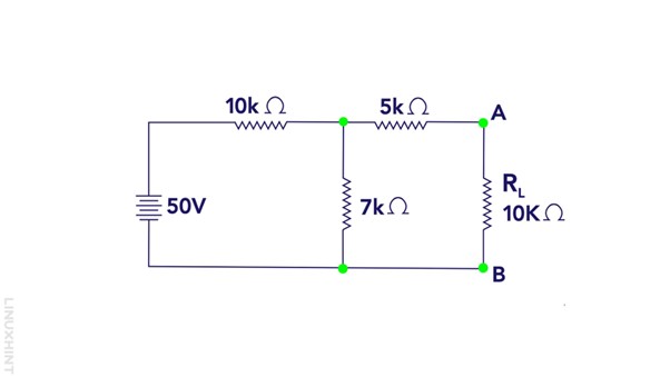
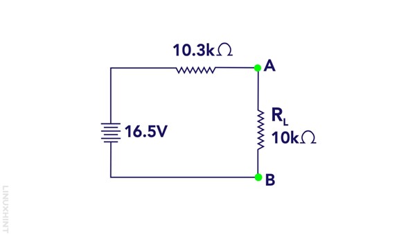
To demonstrate the Thevenin theorem, I have considered a circuit having three resistances in parallel and one load resistance, and one voltage source:
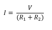
First, we remove the load resistance and calculate the voltage across the Load resistance so since the resistors R1 and R2 are in series as there will be no current through R3. To calculate the current flowing through the resistances:
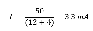
Now placing the values:
Now calculating the voltages across the resistors:
So, the voltage across the R1 and R2 is 16.5 volts which means that the voltage across the load resistance will also be 16.5 V so the Thevenin voltage is 16.5 volts
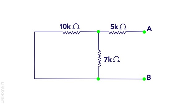
Step 2: Now short the voltage source in the circuit and calculate the Thevenin resistance for that following is the equation:
Now we have our Thevenin voltage and resistance, so now using the ohms law we calculate the load current:
To calculate the load voltage use:
Below is the Thevenin equivalent circuit for the circuit I considered previously:
Conclusion
Thevenin’s Theorem provides a powerful technique to simplify complex DC circuits into more manageable Thevenin equivalent circuits. By replacing mashed-up networks with a single voltage source and resistor, engineers can analyze and understand circuit behavior more effectively.

