Power supplies are energy sources that deliver power to different loads. They are mainly linear power supplies or switching power supplies. The switching power supplies overcome the limitations of linear ones. This article discusses switching power supply in detail.
Switch Mode Power Supply(SMPS)
A switch mode power supply uses semiconductors-based switching mechanisms to regulate the voltage of an unregulated signal. They are regarded as more efficient than their linear supply counterparts since they have reduced power consumption, resulting in heat dissipation.
Power Supply
A power supply, also known as a power supply unit, receives power from a source and distributes it to a load. The terms power source and power supply are the same and can be used in place of one another.
A power source, such as a battery, is an entity that stores power to give it to various units as needed. A power supply is a device that converts the energy gained from other power sources into a utilizable form for the operation of electrical or electronic circuits.
Although electrical power sources may include energy, the use of a power supply is required to transmit it to the loads. This is because it converts these electrical energies into the utilizable form for loads.
Power supplies can be of two categories:
Linear Mode Power Supply with Linear Regulation
A linear power supply is used to transform an unregulated alternating current or direct current input signal into a regulated direct current output signal. However, the operating principles of LPS and SMPS differ. It is also regarded as a less efficient solution since continual heat generation wastes power. It has a series voltage regulator for low-output power applications.
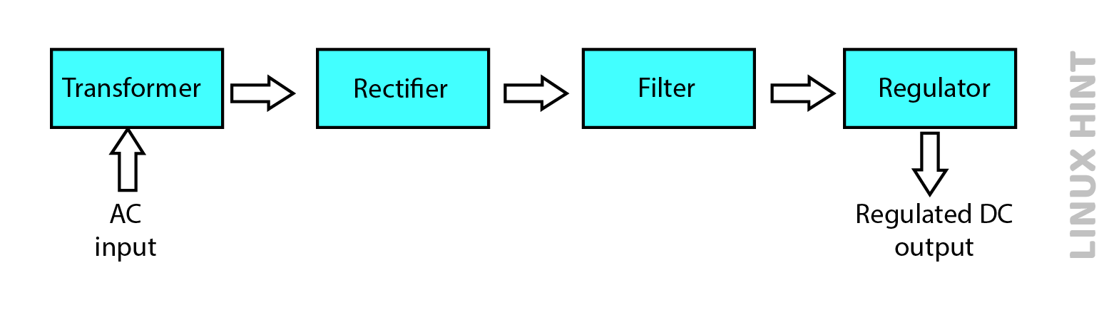
The applied alternating current input voltage is first stepped down by a transformer in the case of a linear power supply. A diode rectifier is then utilized to rectify the alternating current signal. A capacitor filter is used to filter the signal after its rectification. After being filtered, the unregulated DC signal is fed into the linear voltage regulation circuit, which outputs a regulated DC signal.
Essentially, SMPS was created to offset the disadvantage of LPS due to its high efficiency. Furthermore, unlike linear power supplies, it is appropriate for applications requiring higher output current or voltage due to the incorporation of switching regulators. This is why the switch mode power supply is so termed.
Switch Mode Power Supply with Semiconductor Based Regulation
Batteries are used to power different types of electronic and electrical loads. However, batteries do not produce controlled power since their voltages are either extremely high or extremely low. As a result, SMPS is employed to obtain regulated DC output.
Compared to linear power supplies that make use of traditional linear methods for voltage regulation, a switch mode power supply uses semiconductor-based switching mechanisms for voltage regulation of an input signal. It is regarded as very efficient since it reduces power consumption, resulting in a reduction in heat dissipation.
A switching transistor (power MOSFET) is used in SMPSs to regulate voltage. The transistor changes between on and off states throughout operation, so that while it is switched on, it conducts current with a minimal voltage drop across it. When turned off, it attempts to prevent the passage of current. As a result, switching between the on (saturated) and off (cut-off) states occurs at a high frequency, and the device functions as an ideal switch.
It should also be noticed that the transformer size decreases at higher frequencies. Due to this the overall size and weight of the SMPS is quite small, which is an edge over linear power supply.
Types of Switch Mode Power Supply
Compared to linear voltage power supplies that always provide step-downs of voltage regulation. The switch mode power supplies provide both step up and step-downs of voltage regulation. As a result, SMPS are further classified as:
Buck Mode Switching Power Supply
It is made of a step-down kind of regulator circuit that converts DC to DC. The term ‘buck’ refers to a reduction or subtraction. It converts higher DC voltages to low DC voltage levels. The basic buck mode switching power supply circuit is shown below:
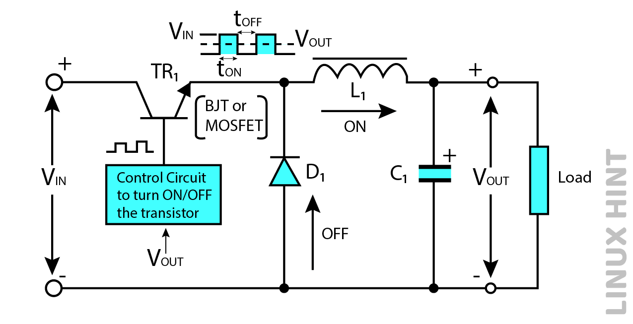
It consists of a transistor T1 connected with a basic signal refining circuit consisting of diode D1, inductor L1, and capacitor C1. When the transistor turns ON, diode D1 is reverse biased, and current flows into capacitor C1 which charges it by passing through inductor L1. When the transistor turns OFF, a reverse voltage appears across its contacts which forward biases the diode D1. The inductor L1 releases its stored magnetic field energy to load and acts as a source of supply till it exhausts all of its energy. Therefore, load continues to receive supply in both OFF and ON states.
Boost Switch Mode Power Supply
It uses a step-up regulator circuit to convert a low-level DC signal to a high-level DC signal. The word boost means to increase or add up, so a boost switching supply levels up the supply voltage while maintaining the same polarity as the input signal. The boost mode switching power supply is shown below:
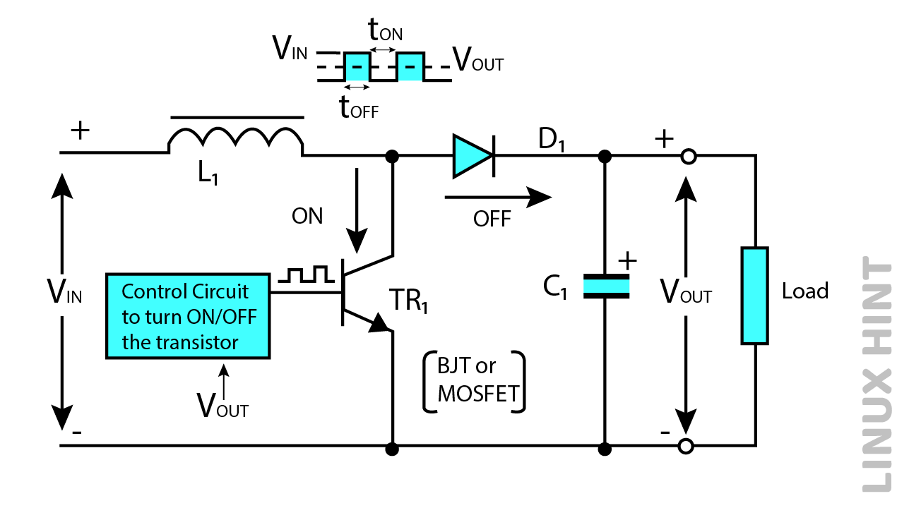
In boost mode switching power supply, transistor TR1 connects in parallel with series inductor L1 and diode D1. When the transistor turns ON, the supply current does not conduct load as it flows through the inductor and a closed transistor switches TR1 back to supply. When the transistor turns OFF, supply voltage VIN conducts the load through inductor L1. The inductor L1 releases its already stored energy as well to the load in the OFF state. Therefore, input voltage and inductor voltage add up together as VIN+VL to supply load.
Buck-Boost Mode Switching Power Supply
This SMPS combines the functions of both buck and boost regulators in a single power supply. The output produced in this configuration is inverted, with a voltage magnitude that can be either greater or less than the supply input depending on the duty cycle. The buck-boost type of switch mode power supply is shown below:
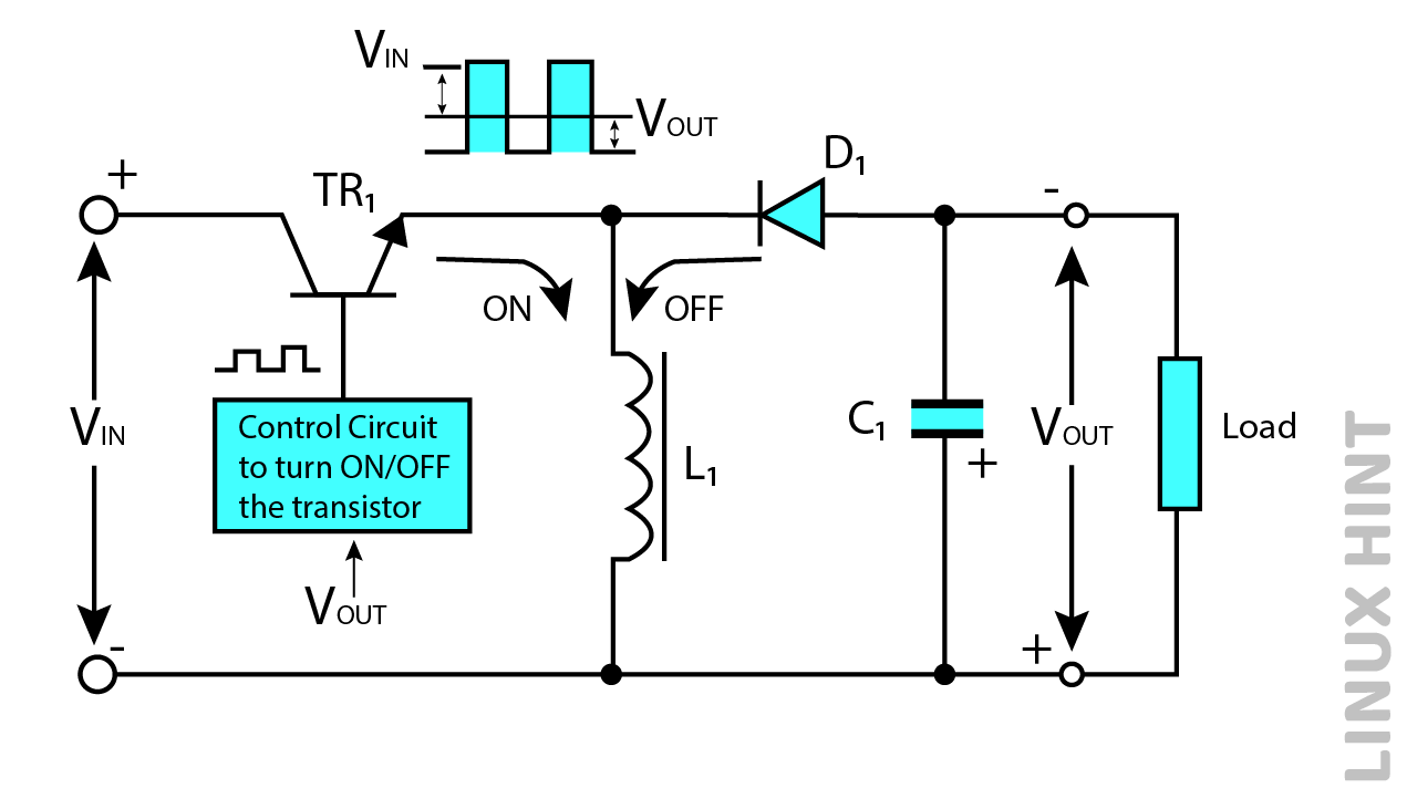
The transistor TR1 is connected in series while inductor L1 and capacitor C1 are in parallel configuration. When the transistor turns ON, the supply current from the source passes through inductor L1 back to the input voltage. In this case, the transistor turns OFF, and the energy stored in inductor L1 releases, supplying load while passing through forward-biased diode D1. Therefore, the load is supplied in both ON and OFF states.
Construction & Working Principle
The operational block diagram for switch mode power supply is shown below:
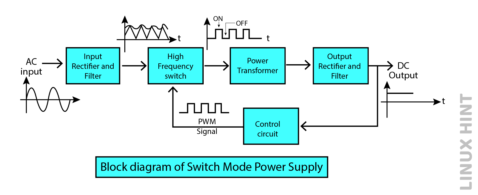
The following are the major components of SMPS:
- Filter and input rectifier
- Power transistor or MOSFET
- Transformer
- Filter and output rectifier
- Control circuit
The input alternating current (AC) signal from the source is supplied to the rectifier and filter. The alternating current (AC) input signal undergoes rectification to produce a direct current (DC) signal, which is further smoothed to eliminate high-frequency noise components. The direct current (DC) output, which remains unregulated, is supplied to the power transistor functioning as a high-frequency switch.
Therefore, based on the switching behavior of the power transistor, a direct current (DC) voltage will be generated at its output. The DC signal acquired at the output of the frequency circuit is then supplied to the high-frequency-based power transformer.
The step-down transformer is responsible for converting the high-voltage signal into a lower-voltage level. This lower voltage level is then supplied as input for the rectifier and filter. The primary function of this process is to eliminate undesirable residuals from the signal, resulting in a regulated direct current (DC) signal as the final output.
The control circuitry functions as the feedback circuit for the entire system. This circuit involves the utilization of a pulse width modulator (PWM) and a comparator. The DC output current from the rectifier and filter is supplied to the control circuit. Within this circuit, the error amplifier functions as a comparator, comparing the measured DC voltage with a predetermined reference value.
The pulse width modulator used in the aforementioned circuit is accountable for producing a pulse width modulated waveform with a constant frequency, wherein the duty cycle of said waveform governs the chopping frequency.
Conclusion
Switch mode power supplies provide regulated DC outputs required for most of the latest motor drives, railway traction, security, and power amplification functions. The efficiency of switched-mode power supplies is greater than linear power supplies and lies between 60% to 95%.