Table of Content:
- A Solid State Relay
- Construction of Solid State Relay
- Operation of Solid State Relay
- Kinds of Solid State Relays
- 1. Types based on Input and Output Circuit
- 2. Types based on Switching Property
- 3. Kinds based on Poles and Throws
- Advantages of Solid State Relay
- Disadvantages of Solid State Relay
- Applications of Solid-State Relay
- Conclusion
A Solid State Relay
A Solid-State Relay is a switching electronic device. It is used to turn ON or OFF a load when its control terminals receive a signal from an external source. Unlike an electromagnetic relay, it does not have moving parts to break the circuit like contacts or springs. In contrast, it offers complete isolation between the control part of the circuit and the load part of the circuit where it needs to be turned ON or OFF.
Construction of Solid State Relay
A Solid State Relay is made up of electronic components like resistors, capacitors, and transistors. It has two types of terminals:
Input Terminals
These terminals are connected to a low-power circuit, and this unit is used as a control unit for switching. These input terminals are separately designed for AC and DC circuits.
Output Terminals
The switching of load is done through output terminals. The output terminals are of two types:
Normally Open Output Terminals
These terminals normally remain open. But when the relay activates, these terminals join together and provide a closed path.
Normally Closed Output Terminals
These terminals are normally closed and current flows through the relay. However, when the relay activates, normally closed terminals become open, and no more current flows through the relay.
The input and output circuit is isolated through an optocoupler or an optoisolator.
Operation of Solid State Relay
A Solid State Relay works by switching the load ON or OFF without establishing direct contact between the input and output circuit. An Optocoupler is used for this purpose. It separated the low-voltage input circuit from the high-voltage output circuit. It has a Light Emitting Diode (LED) at low voltage input circuit.
When a signal is applied to the input circuit of the SSR, it makes the LED emit infrared light. These infrared waves fall on the photodiode or phototransistor at the output end. This photodiode is responsible for converting these light signals to electrical signals, turning the load ON or OFF. For the activation of the optocoupler, the Light Emitting Diode (LED) must be forward-biased, which means the applied voltage should be greater than its forward voltage. Immediately after the optocoupler is switched ON, the output circuit starts conducting.
Kinds of Solid State Relays
Solid State Relays can be classified on three different bases that are listed and explained below
- 1. Types based on Input and Output Circuit
- 2. Types based on Switching Property
- 3. Kinds based on Poles and Throws
1. Types based on Input and Output Circuit
Based on input and output circuits, a solid state relay has three types that are DC to DC Solid State Relay (SSR), DC to AC Solid State Relay (SSR), and DC to DC/AC Solid State Relay (SSR). These types are explained below
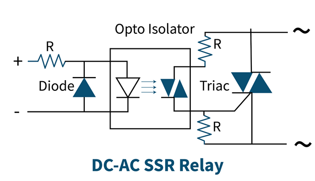
DC to AC Solid State Relay
This type of relay is used to switch high-power AC loads through a low-power DC source. For this purpose, an LED is used that emits infrared waves when forward-biased through the input voltage. These waves fall on TRIAC that converts them to AC electrical signals and current starts flowing in the output circuit that activates the relay.
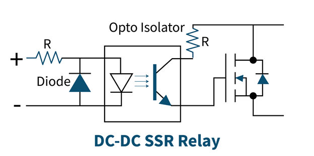
DC to DC Solid State Relay
This type of relay works with a DC input that is of low power, and it switches high-power DC loads. For this purpose, a power MOSFET and a protection diode are used. The power MOSFET conducts in a single direction and makes sure that the load is connected in the correct polarity. A protection diode protects from damage due to reverse polarity. If the load is inductive, a freewheeling diode is used to eliminate any surge in current.
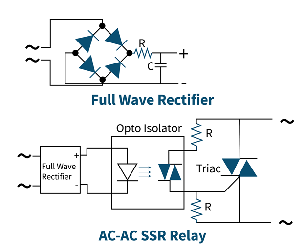
AC to AC Solid State Relay
This type of relay has both AC input and output circuits. To operate the optocoupler, a rectifier is used at the input circuit that converts AC to DC. When Optocoupler is activated, AC starts flowing in the output circuit, which is responsible for the activation of the relay.
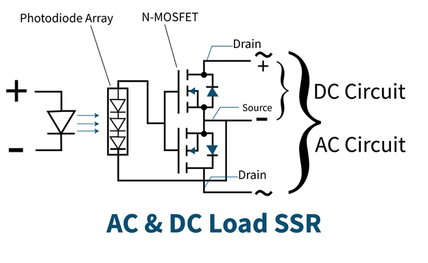
DC to DC/AC Solid State Relay
Both AC and DC loads can be operated using this kind of Solid State Relay. It uses MOSFET with a common source configuration. When the photodiode converts the light signal to an electrical signal, this voltage is applied to the gate and source of MOSFETs. For operating AC load, only drain terminals are used and for DC load, both drain and source terminals are used.
2. Types based on Switching Property
If you classify Solid State Relay taking into account its switching properties, solid state relay has four different kinds named Instant Switching Solid State Relay, Zero Switching Solid State Relay, Peak Switching Solid State Relay, and Analog Switching Solid State Relay. These types are explained below:
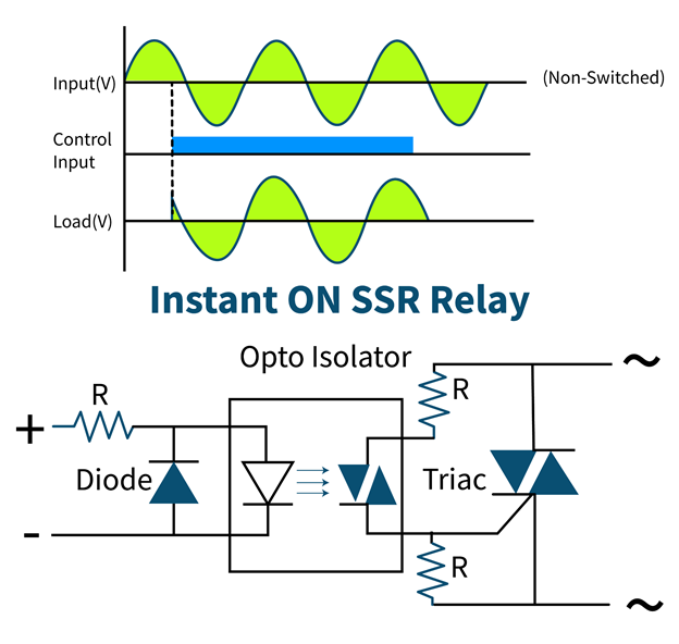
Instant Switching Solid State Relay
This type of relay instantly switches ON as soon as the input voltage is applied and turns OFF at the immediate zero crossing of output load voltage after the input signal is removed.
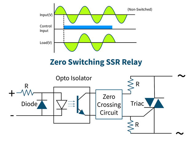
Zero Switching Solid State Relay
As the name suggests, this kind of relay switches ON when the load voltage crosses zero after the application of an input signal. It turns OFF simply at zero crossing of output voltage when the input signal is removed.
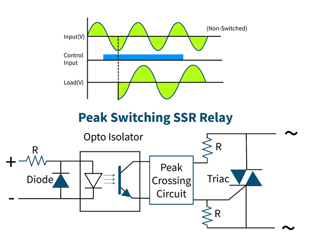
Peak Switching Solid State Relay
This type of relay turns ON at the first peak of output voltage after the input signal is applied and turns OFF similar to instant switching and zero switching relay.
Analog Switching Solid State Relay
The switching of types mentioned above depends on the output voltage; however, switching of analog relays depends on the input voltage. Here, the input control voltage decides the output voltage because they are linked proportionally. It turns on when the minimum input voltage is applied, which is necessary for the starting output voltage. It turns OFF simply as an instant switching and zero switching relay.
3. Kinds based on Poles and Throws
Based on poles and throws, solid state relay has three different types that are
- Single-Pole-Single-Throw (SPST) Solid State Relay (SSR) having (Normally Open-NO Configuration)
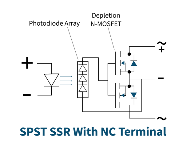
- Single-Pole-Single-Throw (SPST) Solid State Relay (SSR) having (Normally Closed-NC Configuration)
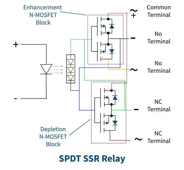
- Single-Pole-Double-Throw (SPDT) Solid State Relay (SSR)
These types are discussed below.
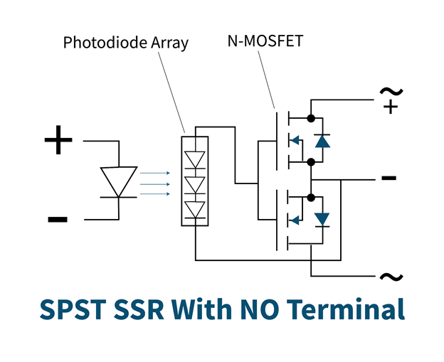
Single-Pole-Single-Throw (SPST) Solid State Relay (SSR) having (Normally Open-NO Configuration)
It has output terminals that are normally open in the absence of an input signal and gets closed when the input control signal is applied. This type uses N-MOSFET for switching load circuits.
Single-Pole-Single-Throw (SPST) Solid State Relay (SSR) having (Normally Closed-NC Configuration)
It is opposite to SPST, normally open configurations. Its output terminals are normally closed and current flows through them in the absence of any input signal. However, when an input signal is applied output terminals get open, and no current flows in the output circuit. This relay uses depletion MOSFET then turns ON at zero voltage and turns OFF at negative voltage.
Single-Pole-Double-Throw (SPDT) Solid State Relay (SSR)
As the name indicates, it has three terminals with two switch throws. Three terminals are NO, NC, and common. When the common terminal of the relay is connected to the Normally open (NO) terminals, the relay energizes. For the relay to be deactivated, the common terminal connects to the NC terminal. There is an extra switching circuit present in this type of relay that does not allow MOSFETs to turn ON at the same time.
Advantages of Solid State Relay
The main advantage of a solid-state relay is that there are no physical contacts, so there is no chance of any tear or spark that makes its lifespan longer than an electromechanical relay. Similarly, it is not affected by vibrations or movements. It also has a fast-switching speed and low power consumption.
Disadvantages of Solid State Relay
The main disadvantage of solid-state relays is the complexity of their design. There is also a small voltage drop at output terminals and a small leakage current when OFF. Furthermore, it also dissipates a large amount of heat.
Applications of Solid-State Relay
The main objective of using Solid State Relays is the switching of high load Alternating Current (AC). They are also used in controlling power, such as motor speed controllers and fan dimmers. Moreover, they are used as temperature controllers in heaters.
Conclusion
Solid State relays are very useful electronic devices that are an improved version of electromechanical relays. They are used for switching without actual contact with the input control circuit and output load circuit. This improves its lifetime. It also has diverse types. These types are used to perform different functions due to slight modifications in their construction.

