Capacitors are vital components in electronic circuits, playing a crucial role in energy storage and signal filtering. Two common configurations for capacitors are series and parallel connections, each with distinct characteristics and applications. In this article, we will explore the concepts of series capacitors and parallel capacitors, provide examples for each, and highlight the key differences between them.
Series Capacitors
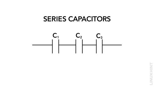
In a series capacitor configuration, two or more capacitors are connected in a chain-like arrangement, where the output of one capacitor is connected to the input of the next. By calculating the reciprocal of each individual capacitance and adding them together, the total capacitance (CT) of capacitors connected in series can be calculated. This relationship indicates that as the individual capacitance increase, the total capacitance decreases. Mathematically, the formula for calculating the total capacitance in series is as follows:

Series capacitors are primarily used for applications such as filtering, frequency tuning, and impedance matching. For example, in an audio amplifier circuit, a series capacitor can be used to block DC voltage, allowing only the AC audio signal to pass through.
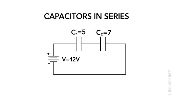
Here is an example of two series capacitors: C1 with a capacitance of 5μF and C2 with a capacitance of 7μF. Applying the series capacitor formula, the total capacitance would be:
Parallel Capacitors
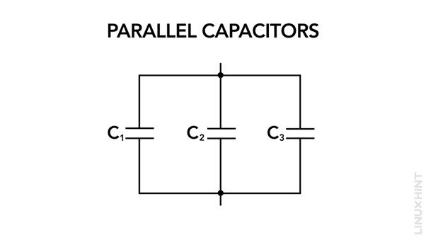
In a parallel capacitor configuration, two or more capacitors are connected side by side, with their terminals connected together. By adding together each capacitor’s individual capacitance, the total capacitance (CT) of capacitors connected in parallel is determined. This relationship shows that as more capacitors are placed in parallel, the total capacitance rises. The formula for calculating the total capacitance in parallel is as follows:
Parallel capacitors are commonly used for applications such as energy storage, power factor correction, and bypassing. For instance, in a power supply circuit, parallel capacitors can be employed to stabilize voltage and filter out noise.
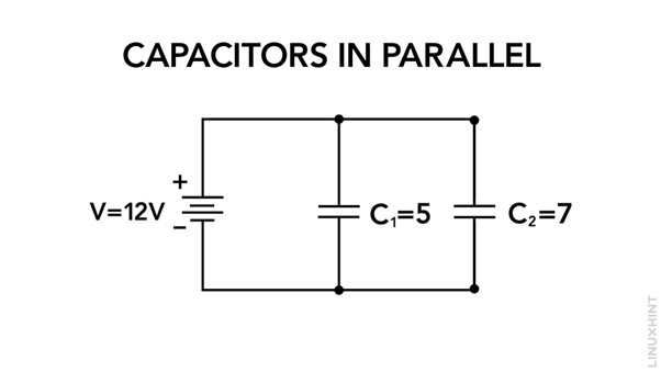
Here is an example of two parallel capacitors: C1 with a capacitance of 5μF and C2 with a capacitance of 7μF. Applying the parallel capacitor formula, the total capacitance would be:
Differences between Series and Parallel Capacitors
To better understand the distinctions between series and parallel capacitors, let’s compare their key characteristics in the table below:
| Characteristic | Series Capacitors | Parallel Capacitors |
| Total Capacitance | Inversely proportional to the sum of reciprocals of individual capacitance | Equal to the sum of individual
capacitance |
| Effective Capacitance | Less than the smallest individual capacitance | Equal to the sum of individual capacitance |
| Capacitor charge distribution | The same charge across all capacitors | Individual charges for each capacitor |
| Applications | High frequency filtering | Energy storage and low frequency filtering |
| Voltage Distribution | Shared | Same across all capacitors |
Conclusion
Series and parallel capacitors offer distinct characteristics in electrical circuits. In series, the capacitance combines inversely, resulting in a smaller overall capacitance. In parallel, the individual capacitance sums up, leading to a larger overall capacitance.


