Today we will discuss how we can connect multiple I2C devices with Arduino Nano and scan their I2C address using the Arduino IDE code.
Introduction to I2C Communication
The Arduino Nano can communicate with other devices using the Inter-Integrated Circuit (I2C) protocol. Data is exchanged via two wires using the I2C protocol. It is widely used in electronics because it allows multiple devices to share a limited number of connections without the need for a separate communication channel.
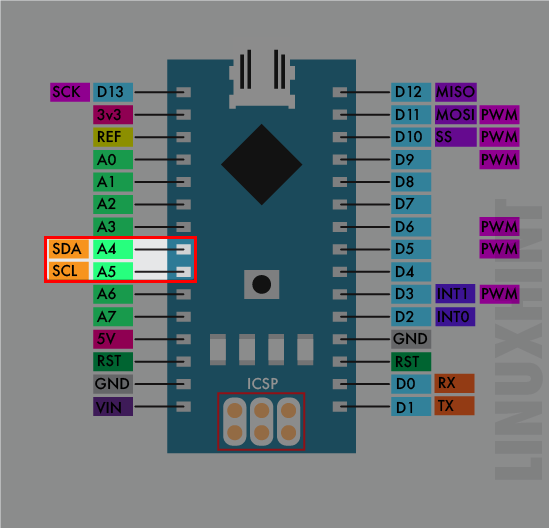
To use I2C on the Arduino Nano the SDA (data pin) and SCL (clock pin) is used. On most Arduino Nano boards, these pins are A4 and A5, respectively. You will also need to include the Wire library in your sketch and initialize the I2C communication using the Wire.begin() function.
I2C is similar in working to UART and SPI. For example, like SPI protocol I2C also has support for single master and multiple slave devices. Similarly, I2C is somehow similar to UART also because of the two wires for communication. UART uses two wires for communication that is Tx and Rx, I2C also uses two wires SDA and SCL for communication and data transfer.
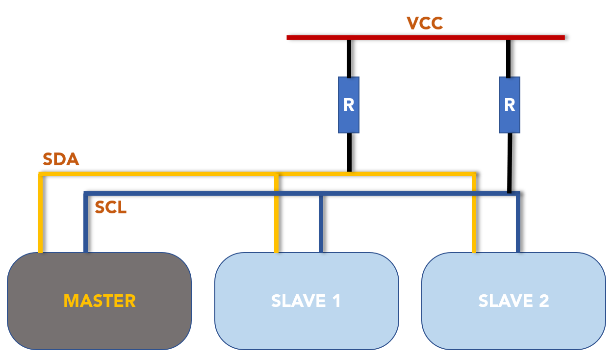
Above image represents controlling two slave devices using a single master. Here a pull up resistor is connected to both SDA and SCL. I2C gives signals with two levels LOW and open circuit. I2C on Arduino Nano is in open circuit mode. Pull up resistor which we used will pull I2C to HIGH level.
Arduino Nano uses two lines for I2C communication:
- SDA (Serial Data) – A4 Pin: Line that exchange data between master and slave
- SCL (Serial Clock) – A5 Pin: To send signal to a specific slave a clock signal is used
How To Scan I2C Address in Arduino Nano Using Arduino IDE
The I2C address of a device must be unique because it is used to identify the device on the I2C bus. When a device sends or receives data on the I2C bus, it does so using its unique I2C address. If two devices on the same I2C bus have the same address, it will be impossible to distinguish between them, leading to communication errors and unreliable behavior.
To ensure that each device on an I2C bus has a unique address, I2C devices are typically assigned a fixed address by the manufacturer. These addresses are typically 7-bit or 10-bit values, depending on the specific I2C protocol being used.
Devices that use the I2C protocol have unique addresses ranging from 0 to 127. For example, if we have an LCD screen with the same I2C address, we will be unable to communicate between them using the same Arduino board.
Now we will interface two I2C devices with Arduino Nano and find the I2C address using the Arduino code.
Schematic
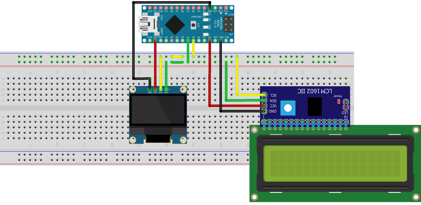
Below image shows schematic of Arduino Nano with OLED and I2C LCD display connected at A4 and A5 pin of Arduino Nano. SDA pin is at A4 and SCL pin corresponds to A5 of Arduino Nano.
The connection pins of Arduino Nano with OLED and I2C LCD is:
| OLED Display | Arduino Nano Pin |
|---|---|
| VCC | 3V3 |
| GND | GND |
| SCL | A5 |
| SDA | A4 |
| I2C LCD Display | Arduino Nano Pin |
|---|---|
| VCC | 5V |
| GND | GND |
| SCL | A5 |
| SDA | A4 |
Code
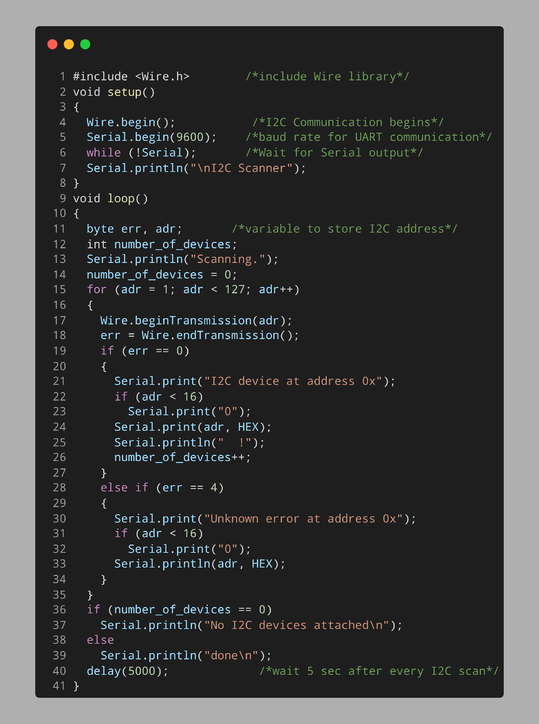
Open Arduino IDE, connect the Nano board and upload the given code to scan the I2C address of the OLED and I2C LCD screen.
void setup()
{
Wire.begin(); /*I2C Communication begins*/
Serial.begin(9600); /*baud rate for UART communication*/
while (!Serial); /*Wait for Serial output*/
Serial.println("\nI2C Scanner");
}
void loop()
{
byte err, adr; /*variable to store I2C address*/
int number_of_devices;
Serial.println("Scanning.");
number_of_devices = 0;
for (adr = 1; adr < 127; adr++)
{
Wire.beginTransmission(adr);
err = Wire.endTransmission();
if (err == 0)
{
Serial.print("I2C device at address 0x");
if (adr < 16)
Serial.print("0");
Serial.print(adr, HEX);
Serial.println(" !");
number_of_devices++;
}
else if (err == 4)
{
Serial.print("Unknown error at address 0x");
if (adr < 16)
Serial.print("0");
Serial.println(adr, HEX);
}
}
if (number_of_devices == 0)
Serial.println("No I2C devices attached\n");
else
Serial.println("done\n");
delay(5000); /*wait 5 sec after every I2C scan*/
}
Code started by including the Wire library that helps Nano to establish I2C communication with devices. Next baud rate is defined for serial communication.
In the loop section variable err and adr is defined. Two variables will store the I2C address after scanning. A for loop is defined which scans the I2C addresses of devices attached to Arduino Nano.
After scanning the I2C address it will be printed on the Arduino serial monitor. The displayed I2C address will be in HEX format.
Hardware
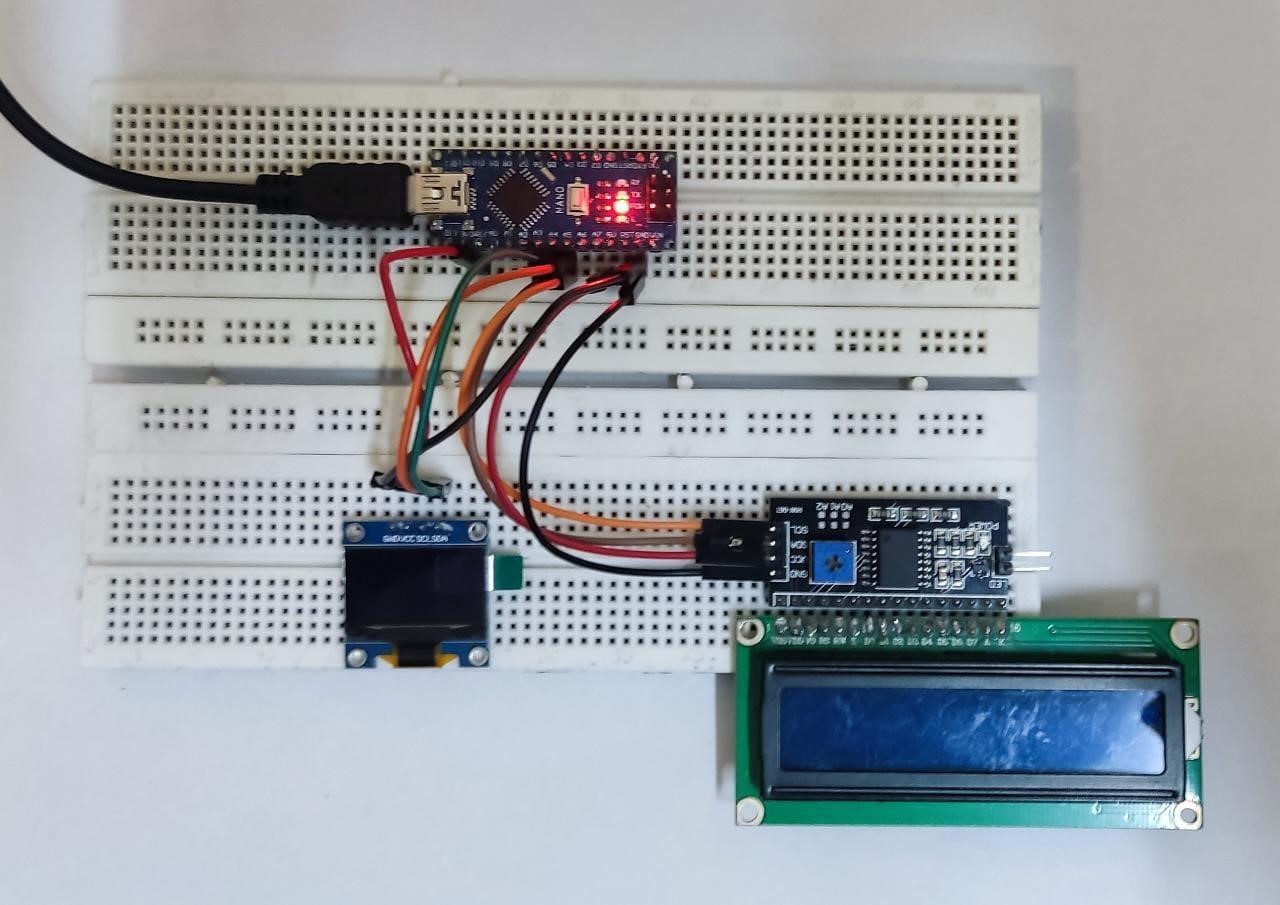
Below image shows the OLED 0.96-inch I2C display and I2C LCD screen is connected to Arduino Nano at GPIO pins A4 and A5. Vcc and GND of both displays are connected to Arduino Nano 3V3/5V and GND pin.
Output
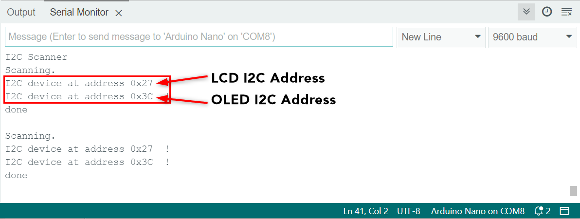
Serial monitor displayed the I2C address of the OLED and I2C LCD displays. Both have separate I2C addresses which means we can use them together on the same Arduino Nano board.
However, if we have devices with the same I2C address we can change their address. To do this look for the datasheet of a specific sensor.
Both OLED and LCD I2C addresses are obtained using Arduino Nano.
Conclusion
Scanning an I2C address before connecting multiple I2C devices with Arduino is important as two devices with the same address cannot communicate over a single I2C bus. This article includes the I2C scanning code using which any of the I2C device addresses can be found which is connected to the Nano board.

