The RGB module is used to generate the different colors by mixing the three primary colors which are red, green, and blue. The module’s output is dependent on the “RGB color model” according to which we can create different shades of colors by mixing the primary colors in a specific proportion. In Arduino, we can interface the RGB module to get different color schemes of the colors which can be used for different purposes.
The RGB module is similar to RGB LEDs so, in this write-up, we will explain the method by which we can interface the RGB module to produce different color shades.
How to use RGB module with Arduino
The RGB module is similar in construction to the RGB LED, so understanding the usage of any of them with Arduino is enough to use the other. We will consider the RGB module; which is of two types, one is a cathode-common RGB module and the other is anode-common RGB. From the name, it is clear that in one module, the cathode is common and in later, an anode is common.
The working of both types is similar, the only difference is in connection like in the cathode RGB module we have to connect one leg to the ground, and in the anode RGB module, the one leg is connected with 5 volts.
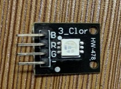
In the figure above, the negative (-) sign is indicating, it is a cathode common RGB module.
How to create a new color shade
We have a color chart available on the internet as well and it is given in the next section, for different colors, there are different values of primary colors as a result of which we can visualize that color. For example, if we want the white color shade, we have to use the maximum values of all primary colors which are 255 in decimal, as a result of which we can get the white color. There are values of some other colors given in the figure:
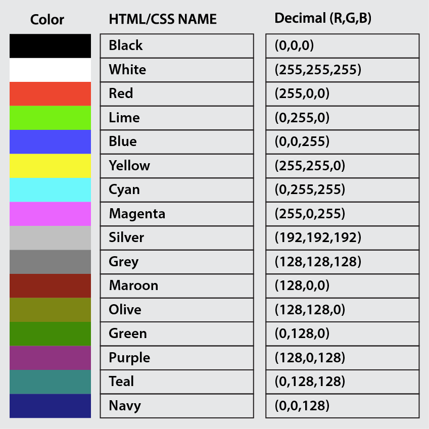
In the above figure, the colors and the values to have them in hexadecimal and decimal are given.
Arduino code to control the RGB light
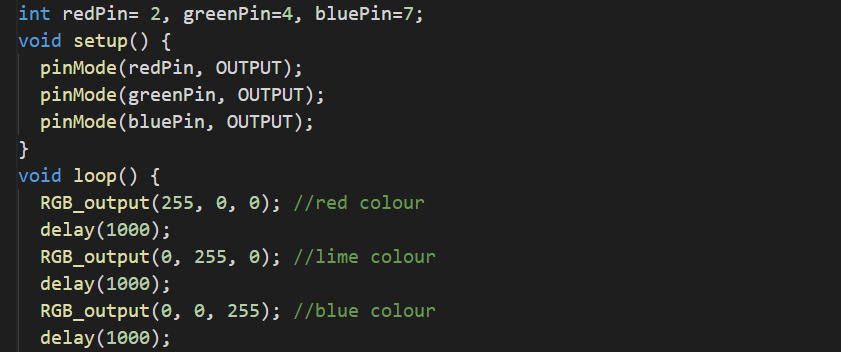
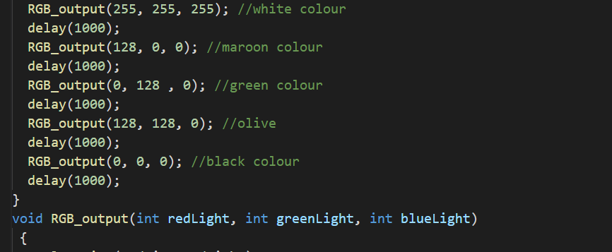
We will use the following Arduino code for getting different colors using the RGB module:
void setup() {
pinMode(redPin, OUTPUT);
pinMode(greenPin, OUTPUT);
pinMode(bluePin, OUTPUT);
}
void loop() {
RGB_output(255, 0, 0); //red color
delay(1000);
RGB_output(0, 255, 0); //lime color
delay(1000);
RGB_output(0, 0, 255); //blue color
delay(1000);
RGB_output(255, 255, 255); //white color
delay(1000);
RGB_output(128, 0, 0); //maroon color
delay(1000);
RGB_output(0, 128 , 0); //green color
delay(1000);
RGB_output(128, 128, 0); //olive
delay(1000);
RGB_output(0, 0, 0); //black color
delay(1000);
}
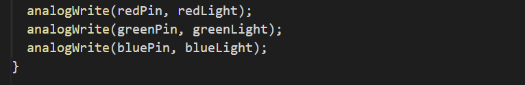
void RGB_output(int redLight, int greenLight, int blueLight)
{
analogWrite(redPin, redLight);
analogWrite(greenPin, greenLight);
analogWrite(bluePin, blueLight);
}
In the above code, we have used different functions:
void setup(): We declared three digital pins, 2, 4, and 7 as the output pins.
void RGB_output(): This is a user-defined function, in which we passed three integer values and set the proportion of every color according to which it glows to have a shade like for white color, we will pass 255 in each parameter so every primary color will bright according to its full value and as a result of it, we get a white color in output.
void loop(): Here we called the function repeatedly with a delay of one second.
Simulation and Hardware
For the circuit of the RGB module with Arduino, we need the following components:
- The resistors of 220 ohms
- Connecting wires
- Breadboard
- RGB module
- Arduino Uno
The circuit diagram will be:

In the above circuit, we have connected three resistors in series with each pin of Green, Blue, and Red, and the common module is connected to the ground because it’s a common cathode module. The resistors are connected to digital pins of 2, 4, and 7 of Arduino.
In the simulation of the above circuit, we used the cathode-common RGB LED so we connected the common point with the ground:
The hardware configuration is:
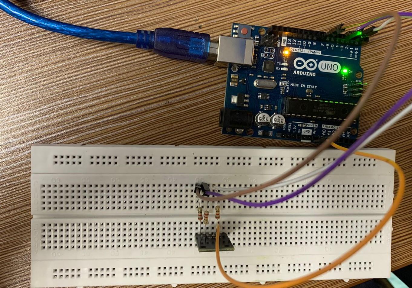
In the hardware configuration:
- We connected three 220 ohms in such a way that one leg of all resistors are connected with B, R, and G pins of the RGB module, and the other legs of all resistors are connected to Arduino Uno pins 7, 4, and 2.
- The negative “-” point of the RGB module is connected to the ground pin of the Arduino because it is a common-cathode RGB module
The working simulation of the hardware configuration is:

Conclusion
The interface of the RGB module with Arduino is a good project for understanding the RGB color module in which we can create different shades of colors by changing the values of three basic colors. The RGB module and RGB LED both work similarly so understanding one is enough to understand the usage of the other. In this write-up, the usage of the RGB module with Arduino is explained and we used the cathode common RGB module.