Relays are used to open or close the different electrical circuits. Electrical relays can have multiple closing or opening contacts, and they can operate different switching operations simultaneously. This article describes relays and their different switching configurations.
Electrical Relays
Electrical relays refer to devices that are utilized in electrical systems to control the flow of electric current by opening or closing circuits. Relays can be of different designs, sizes, and power ratings. Electrical relays possess a high degree of suitability for an extensive range of applications. Relays possess the capability to accommodate either solitary or numerous contacts within a singular package. The higher-sized power relays are mostly utilized for applications involving higher voltages or current switching, commonly referred to as “contractors”.
Working Principle
Relays are specifically engineered to perform two fundamental tasks. One of the devices is designed for low-voltage applications, while the other is specifically intended for high-voltage applications. In the case of low-voltage applications, the relay is specifically engineered to mitigate the noise present throughout the entirety of the circuit. High-voltage applications are primarily engineered with the objective of mitigating the occurrence of arcing phenomena.
The electrical relays can be categorized into two major categories:
Electromechanical relays
Electromechanical relays are devices that utilize both electrical as well as mechanical components for controlling the flow of current in an electrical circuit. Electromechanical relays, as their name implies, are devices that operate through the combined utilization of electrical and mechanical principles. The fundamental principle underlying the operation of a relay switch is the conversion of an electrical control signal into a mechanical force, specifically a pulling force, by the use of a magnetic flux. The most prevalent and elementary configuration of electrochemical relays consists of a coil that is energized and looped around a core composed of permeable iron. The term “energizing coil” is alternatively referred to as the primary circuit.
Construction of Electromechanical Relays
The construction of an electromechanical relay involves the assembly of many components to create a functional device capable of switching electrical circuits, as shown below:
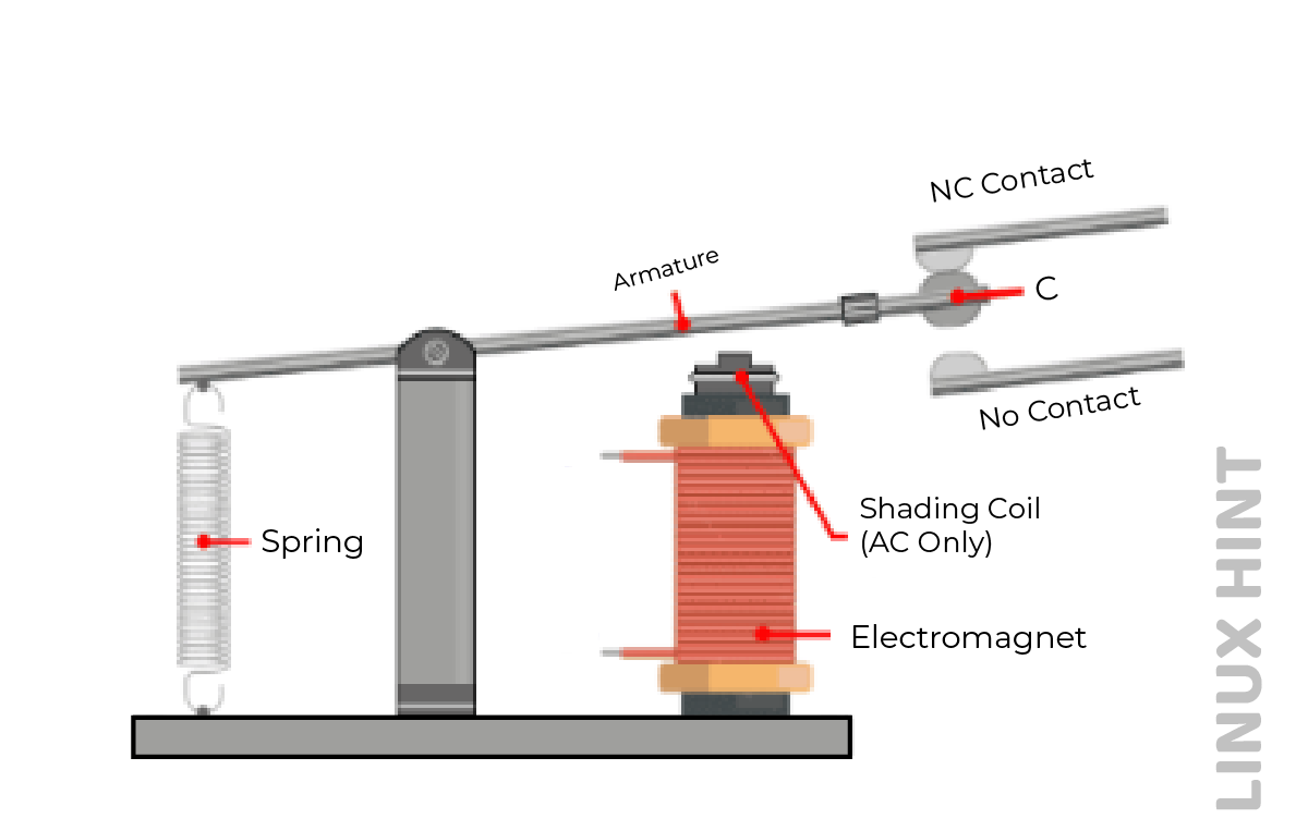
Relays can be configured in two distinct modes, commonly called NC(Normally Closed) and NO(Normally Open) states. There are two types of connections in every contact pair: Normally Open (NO) or break contacts, and Normally Closed (NC) or make contacts.
In the default state, the contacts are in the open position and are only closed when the field current is activated. In the default state, the switch contacts are attracted to the inductor coil. The coil is a crucial component of an electrical relay. The coil is responsible for the conversion of electrical current into an electromagnetic flux. Magnetic fluxes are employed for the mechanical activation of the relay’s contacts. One of the primary challenges associated with relay coils is their characteristic of being “highly inductive loads.” The relay coil is often constructed using wire coils.
When an electric current passes through a coil, it gives rise to the generation of a self-induced magnetic field in its vicinity. When the current is switched to the “OFF” state, a significant back electromotive force (emf) is generated. “Normally Open” and “Normally Closed,” are also known as Make and Break Contacts, about the condition of the electrical contacts in a relay when the coil is not powered, meaning that no supply voltage is connected to the relay coil.
Relay contacts are fabricated with conductive components that facilitate the flow of electric current upon contact. The design of these entities closely resembles that of a switch. Upon the initiation of contact opening, the resistance between the contacts experiences a significant increase. Therefore, an open circuit state arises, leading to the absence of electrical current flowing through the relay.
The mobile components of an electrochemical relay will experience deterioration and ultimately cease to function, or the relay may become rendered inoperable due to the continuous occurrence of arcing and erosion. Moreover, these devices exhibit electrical noise and are prone to contact bounce, thereby impacting the functionality of the electrical circuit.
There can be three different types of relay contacts:
- The Normally Open Contact (NO), alternatively referred to as a make contact, is a commonly used term in electrical engineering. The contact will establish an electrical connection when the relay is energized. The circuit is interrupted when the relay is in a deactivated state.
- The Normally Closed Contact (NC), also referred to as the break contact, is a commonly used term in electrical circuits. The role of the mentioned entity is contrary to that of the normally open (NO) contact. Upon relay activation, the circuit becomes disconnected.
- “Change-over” (CO) and “double-throw” (DT) refer to a type of electrical switch. Contacts are utilized to regulate the operation of a normally open (NO) contact and a normally closed (NC) contact, both of which share a common terminal. This implies that they are employed for the regulation of two distinct circuit configurations. The contacts are referred to as “break before make” and “make before break” based on their respective types.
Solid State Relay (SSR)
It is an electronic switching device that is capable of controlling high-power electrical loads without the use of mechanical contacts. It utilizes solid-state components
The solid-state relay is devoid of any mechanical components that exhibit motion. The equipment in question is exclusively electronic. The relay type under consideration does not incorporate any moving components, as the traditional mechanical contacts have been substituted with power transistors, thyristors, or triacs.
The relay’s exceptional reliability, long lifespan, and low electromagnetic interference can be attributed to the absence of any moveable components. The utilization of solid-state relay technology offers improvements in terms of speed and accuracy as compared to traditional electromechanical relays. The power requirements for controlling solid-state relays are typically low to ensure compatibility with a wide range of integrated circuit families.
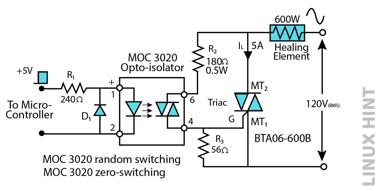
One of the most common configurations of solid-state relays is shown above. MOC3020 and MOC3041 are both opto-triac switching isolators. MOC3020 is a regular switching isolator while MOC 3041 is an opto-isolator with in-built zero crossing detection for limiting any inrush currents. Both diode D1 and resistor R3 protect the circuit from reverse currents and transients. Solid state relays can operate on a maximum switching frequency of 10Hz.
NPN Relay Switch Circuit
In a conventional NPN relay switch circuit, the coil is activated using an NPN transistor switch. When there is no base voltage of the transistor or the base is at zero, the transistor will stay in the cut-off region and function as an open circuit switch. In the present scenario, there is an absence of Collector current and the relay coil is in a state of de-energization.
If there is an absence of electrical current entering the Base, it follows that there will also be an absence of electrical current passing through the relay coil. When a substantial positive current is applied to the Base to achieve saturation in the NPN transistor, the resulting current begins to flow from the Base to the Emitter.
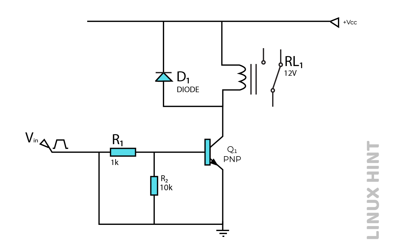
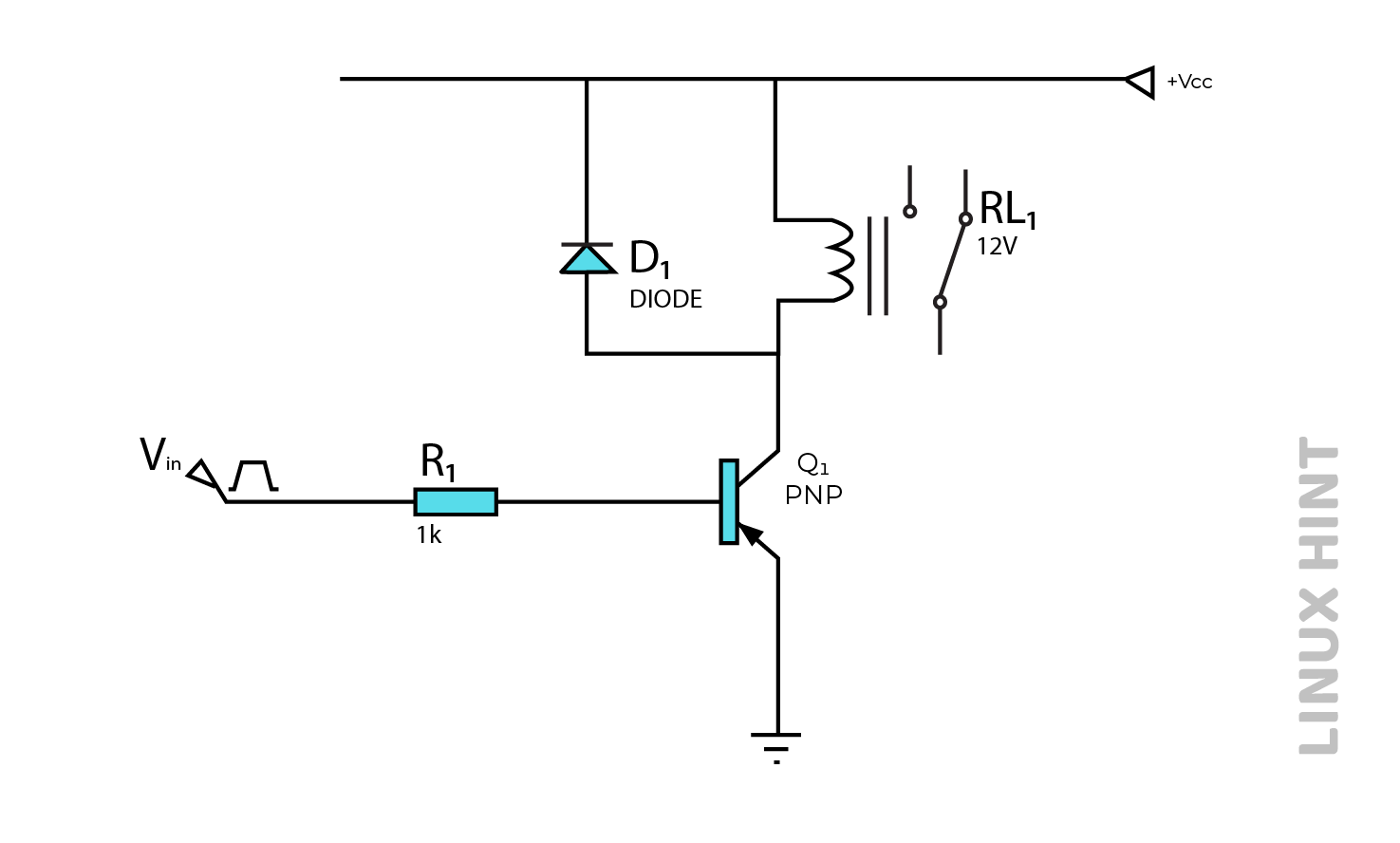
PNP Relay Switch Circuit
This switch circuit works on the utilization of an operating voltage with opposing polarities. The functionality of this circuit bears a resemblance to that of an NPN relay switching circuit, as it possesses the capability to regulate the coil of the relay. In the case of the PNP type, it is necessary for the Collector-Emitter voltage to be negative to facilitate the flow of current from the Emitter to the Collector.
N-Channel Relay Switch Circuits
The operational characteristics of MOSFET relay switching closely resemble those of a Bipolar Junction Transistor (BJT) switch. The primary distinction among operations lies in the fact that MOSFETs are devices that are operated by voltage. Nevertheless, it is important to note that the Gate is completely isolated from the Drain channel.
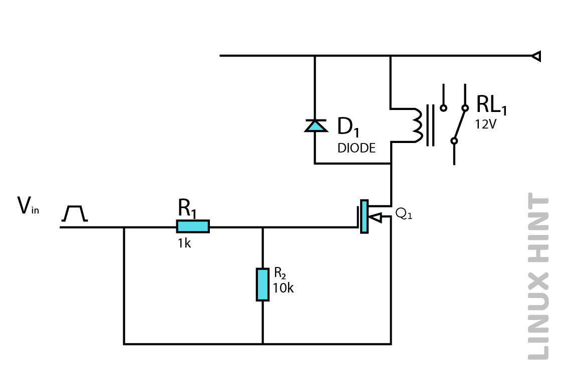
The activation of the MOSFET occurs when a positive voltage connects with the gate terminal, causing it to transition to an “ON” state. Conversely, the application of a negative voltage to the gate terminal results in the MOSFET transitioning to an “OFF” state. This characteristic renders it well-suited for use as a MOSFET relay switch.
P-Channel Relay Switch Circuits
In contrast to the N-channel Enhancement MOSFET, this particular device exclusively functions with negative gate voltages. In the given arrangement, the source of the P-channel is connected to the positive voltage supply, denoted as +Vdd, while the drain is connected to the ground. Both components are interconnected by the coil of the relays. When a higher voltage level is provided to the gate, the P-channel MOSFET will be switched to the “OFF” state as a result.

Conclusion
Relays are used both for low voltage applications and high-voltage applications. In low voltage, relays limit noise in the circuit while in high voltage relays reduce arcing during switching circuits. Relays can be used in various switching arrangements. These include NPN, PNP, N-Channel and P-Channel relay switch circuits.