A three-phase rectifier converts the three-phase AC supply into a constant DC supply output using diodes in the circuit. These rectifiers can do different rectification functions, including half-wave rectification and full-wave rectification of three-phase supply. This article discusses three-phase rectifiers in detail.
Three Phase Rectification
A three-phase rectifier provides rectification of three phases of AC supply. Three-phase supply can be considered as a group of three single phases. Therefore, three-phase rectification will follow three cases of single-phase rectifiers in one circuit.
Half Wave Three Phase Rectification
Half-wave rectification means that only halves of the input AC supply cycles will be rectified at the output:
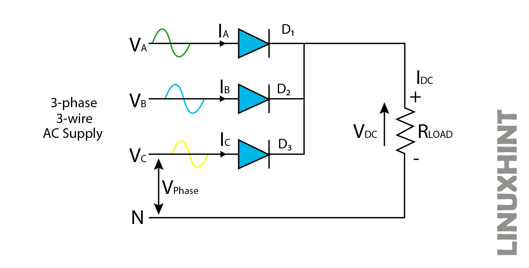
It consists of three diodes D1, D2, and D3 connected to three of the phases of AC supply. The anodes of diodes are connected to three phases of supply, while the cathodes of diodes are connected at a common point. The load is connected between the common point of diodes acting as the + terminal, and the – terminal of the load is connected to the neutral supply. In the above configuration, each of the three diodes conducts one-third of the input AC cycle.
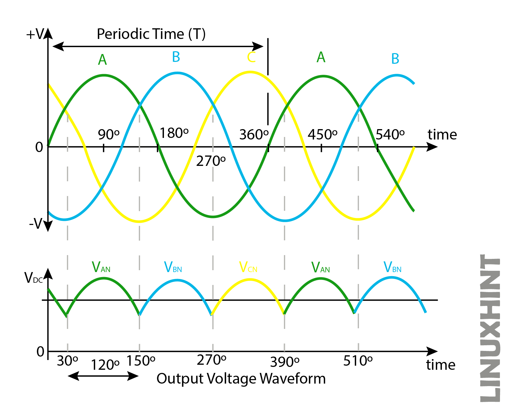
This is because each diode experiences different instants of input AC waveforms that only the diode having a more positive part of the input waveform will conduct while others will remain in the off state. This is shown by the waveforms above.
Full Wave Three Phase Rectification
Full wave rectification provides the conversion of a full wave of input AC cycles into stable DC output. This configuration requires six diodes, while the conduction takes place at different instants by a complete diode pair.
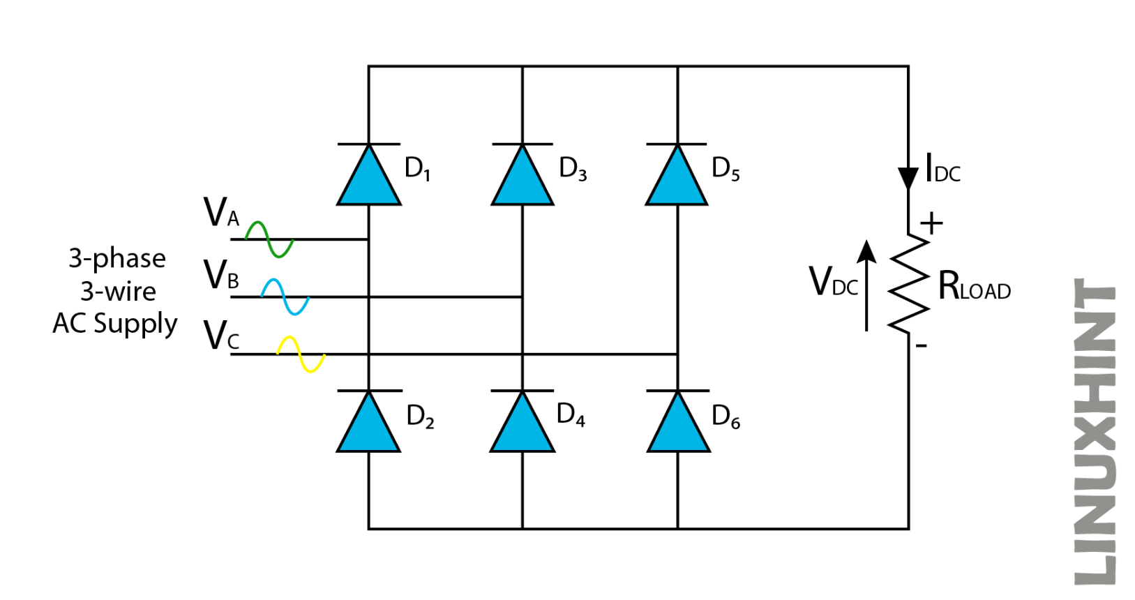 In the above configuration, each phase of the input AC supply connects between the two diodes. A diode pair conducts in this case, except for a single diode in a half-wave rectification case. Three different full-wave bridge rectifiers operate in the above circuit. The first full wave bridge rectifier network is formed between the first two phases A and B while the second full wave bridge rectifier network is formed between the next two phases B and C. Third bridge rectifier network is formed between phases C and A. Therefore, full wave rectification is achieved across all the phases in this configuration.
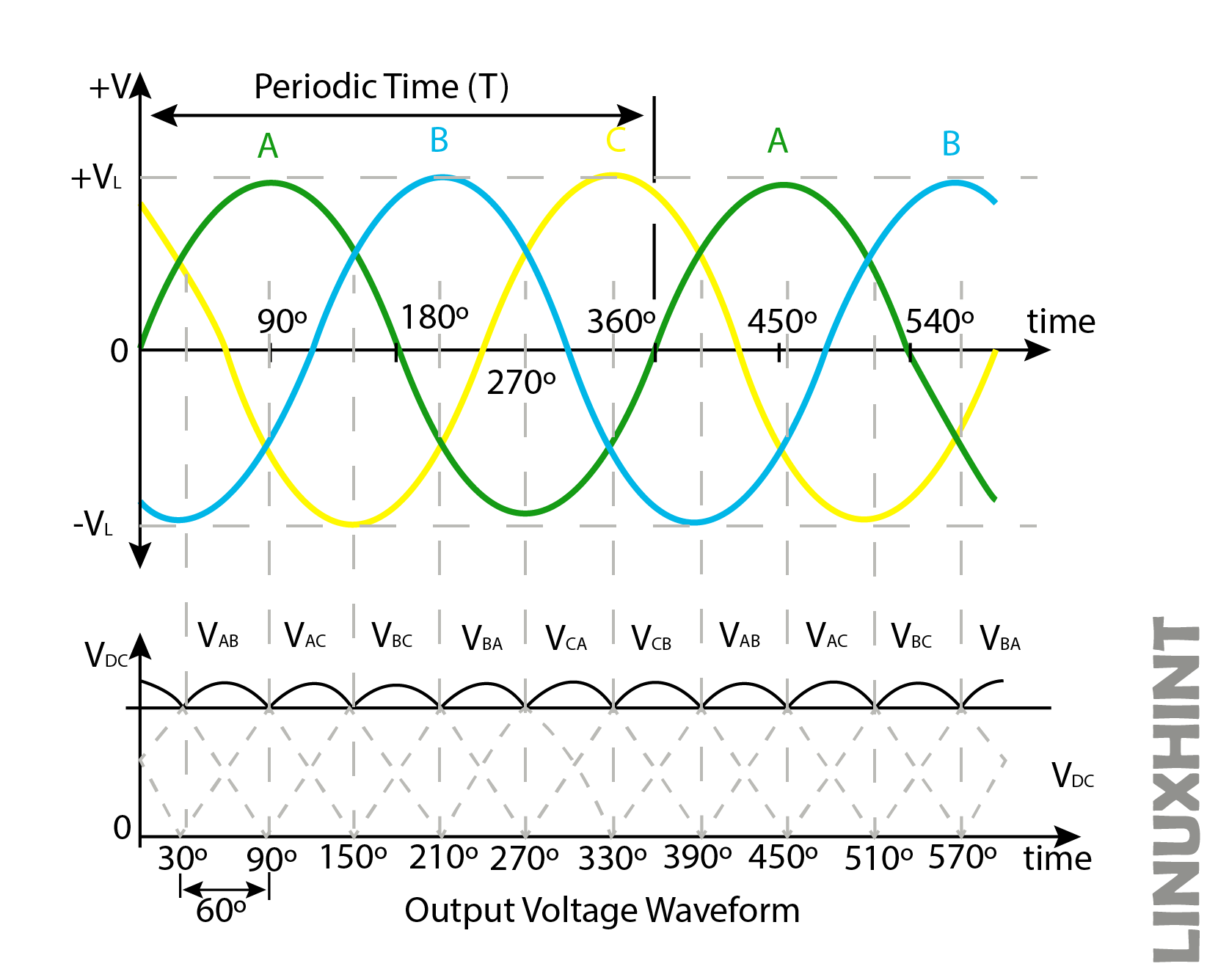
In the above configuration, each diode conducts for 120 degrees or one-third but as a pair of diodes is involved for conduction in this case, each pair conducts for 60 degrees in this case or one-sixth of a cycle as shown in the above waveform.
Example: Half-Wave Rectification
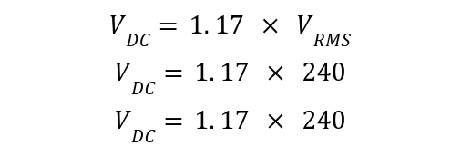
A 240VAC three-phase star-connected transformer is connected with a load of impedance of 60 ohms in a three-phase half-wave rectifier. Calculate the average DC load voltage, load current, and average Current per Diode. The Average DC load voltage is given by:

The load current:

For the three-phase half-wave rectifier, three diodes are used, the average current is given as:

Example: Full Wave Rectification
A three-phase 145V, 50Hz supply is connected with a full wave bridge rectifier, with a 250ohms resistor. Calculate the DC output voltage and load Current. The line-to-line peak voltage is given by:
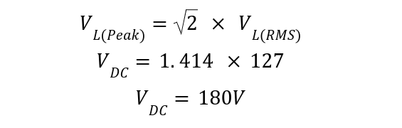
The phase-to-neutral voltage of each phase is given as:
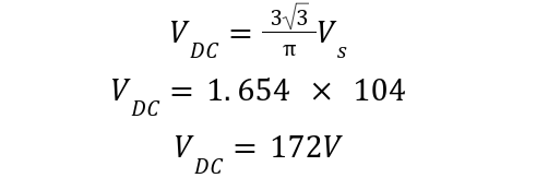
 Thus, DC output voltage:
Load current is given by:

Conclusion
To convert the balance three-phase supply into the constant DC supply using the diodes is referred to as three-phase rectification. To perform this rectification three diodes are required, that is one for each phase in the case of half-wave rectification, as in the case of full wave each phase requires two diodes. The full wave rectification is beneficial as it enhances the bridge efficiency and decreases the ripple content.