Pull Up Resistors
Generally, in the case of an open circuit, there is no contact with external voltages and it means no input signal can reach the microcontroller or logic gates in an open switch state. It means that the inputs to the microcontroller or logic gate from external supply shall be a definite zero. However, it is not the actual case in electronic circuits. The inputs keep on floating their values in this case. To ensure that an open circuit voltage appears at switch terminals in the open circuit case, a resistor is added between the voltage supply and the input pin of the microcontroller as shown below:
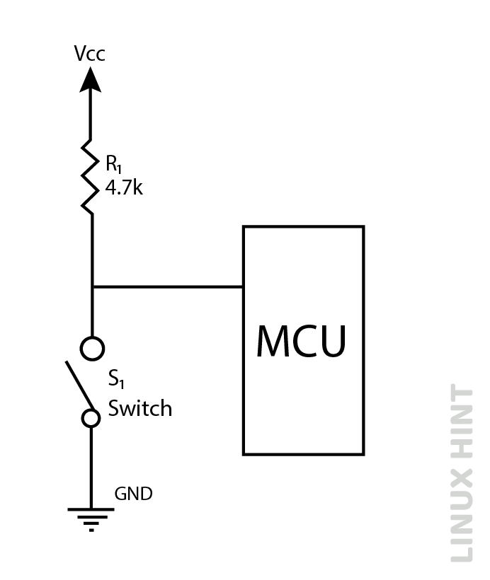
This resistor pulls up the input voltage to the microcontroller to a definite level of Vcc. In the closed state of the switch, the voltage at the input of the microcontroller is grounded. The presence of a pull-up resistor also adds an impedance between supply voltage Vcc and ground. Otherwise, when the switch is closed, a short circuit will appear between Vcc and ground in the above configuration.
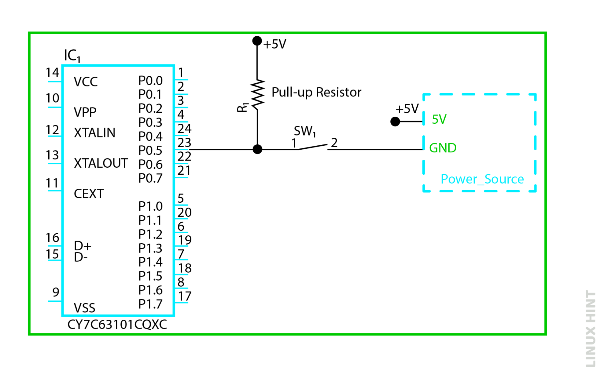
The more detailed version of the micro-controller unit with a pull-up resistor connected between the voltage supply and input pin P0.5 is shown in the figure above. The switch S1 when closed, connects pin P0.5 to the ground providing a zero level or low state. Direct contact of the microcontroller pin to the ground point may lead to a short circuit but in this case, the pull-up resistor draws a portion of the current to limit the short circuit.
Pull-up resistors, therefore prevent short circuits when output is connected to the ground in a closed state. In an open state, the pull-up resistors assist in pulling up the high-level state which would otherwise float between high and low values and produce unexpected results.
Pull Down Resistors
These resistors are used to pull down the input states to low ground levels. Pull-down resistors are connected between the ground and input terminals of microcontrollers and logic gates as shown in the below figure.
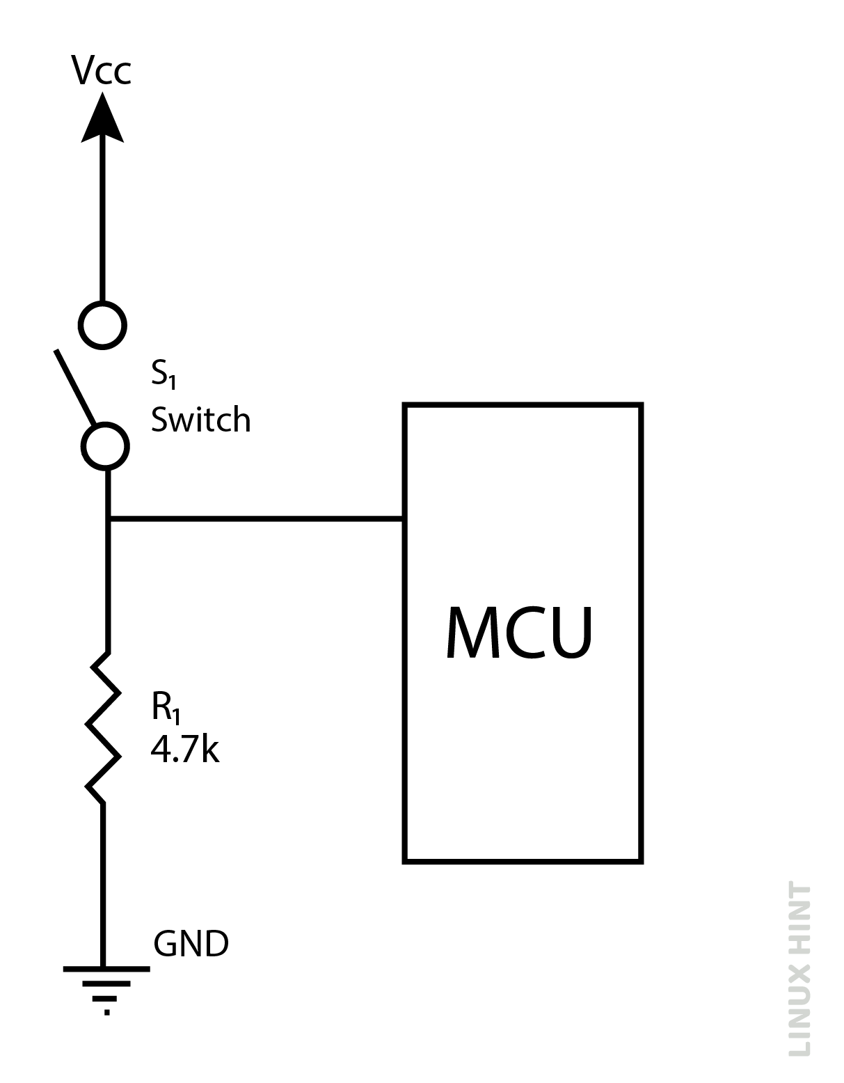
When the switch is in the closed state, the supply voltage Vcc is connected to the input terminal of the microcontroller. However, when the switch is opened, a pull-down resistor functions to settle the voltage down to the ground or zero level.
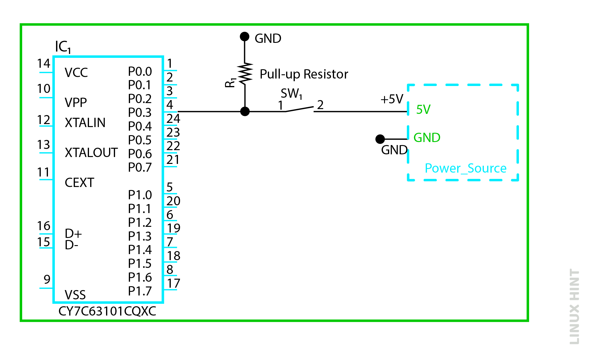
The more detailed version of the micro-controller unit with a pull-down resistor connected between the voltage supply and input pin P0.3 is shown in the figure above. The switch SW1 when closed, connects pin P0.3 to the ground providing a zero level or low state. Direct contact of the microcontroller pin to the ground point may lead to a short circuit but in this case, the pull-down resistor draws a portion of the current to limit the short circuit.
Pull down resistors, therefore preventing short circuits when output is connected to ground in a closed state. In an open state, the pull-down resistors assist in pulling down the lower-level state which would otherwise float between high and low values and produce unexpected results.
Operating Voltage Ranges
A high state does not necessarily mean a single high value and therefore low state does not necessarily mean a single low value in the case of digital logic gates. Every digital logic gate has its range of high-state and low-state voltages. Every value in the entire high-state range will keep the logic gate in a high state and vice versa. Therefore, the logic gate will remain in a high state for the entire high-state range of voltages and remain low for the entire range of low-state voltages.
An example of operating voltage ranges for TTL 74LS series digital logic gate is shown below:
| LS-TTL Input Voltage Levels | |
|---|---|
| Logic ‘1’ Input | Vcc= +5.25V max. to +4.75V min. |
| Indeterminate Region | VIL(MIN)=2V |
| Logic ‘0’ Input | VIL(MAX)=0.8V |
In the above figure, VIH(min) is the lowest voltage value to be considered a high state or ‘1’ level. VIL(max) is the maximum voltage value that falls in the low state or ‘0’ level.
Mathematical Expression for Pull-Up Resistors
For single gate or standard inputs of pull-up resistors, the maximum value for the resistor can be calculated as:

For multiple logic gates with pull-up resistors, the current can be multiplied by the number of logic gates.
Comparison of Pull-up and Pull-Down Resistors
Pull-up and pull-down resistors function to either shift up the input voltage or shift down the input voltage.
| Sr No | Pull Up Resistors | Pull Down Resistors |
|---|---|---|
| 1 | Connects between supply voltage and input terminal | Connects between input terminal and ground |
| 2 | Pull ups input voltage to ‘high’ state | Pulls down input voltage to ‘low state’ |
| 3 | Switch is connected between input and supply voltage | Switch is connected between input and ground |
Applications
Pull-up resistors are commonly used in microcontrollers when the input is provided via switches. The latest microcontrollers include added pull-up resistors in their design to avoid any external additions.
An application of two pull-up resistors along with a logic gate is presented below:
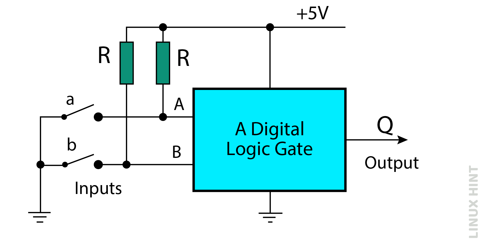
A digital logic gate has two input terminals A & B. The two input resistors are connected between the supply voltage and inputs, which shows the application of pull-up resistors.
When switches A & B are opened, the supply voltage connects the two inputs through these resistors. The resistors oppose any current flow and voltage drop across them, which results in the application of complete 5V to input terminals of logic gates. The +5V input is a complete high state ‘1’ for the inputs of the logic gate.
Similarly, when switches A & B are closed, the inputs are directly connected to the ground, creating a low input state ‘0’ for the input terminals. The supply voltage is isolated through resistors and cannot come in contact with ground in this condition.
Example 1
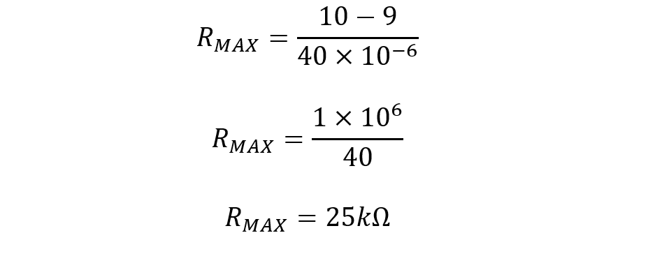
Digital logic NAND gates along with a switch and pull-up resistors have been employed to form a flip-flop. When Vcc=10V, VIH=9V, IIH(max)=40µA, calculate the maximum pull-up resistor value and the current through it.
The maximum value of pull up resistor is given by:

Current across a resistor can be calculated by Ohm’s law:


Example 2
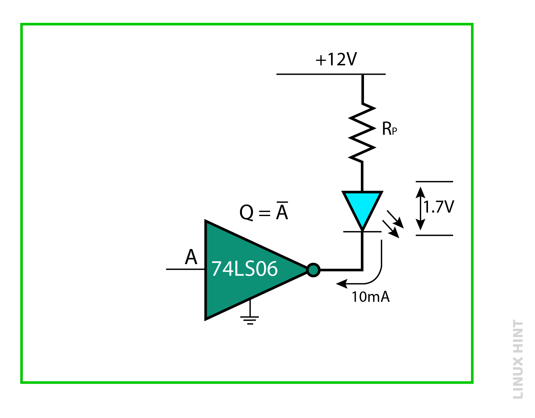
A Hex inverter driver is required to control a single blue color LED-based indicator from a 12V supply. if LED requires 10mA at 1.7V voltage drop and VOL of the inverter in fully-on state is 0.2 volt. Calculate the current limiting pull-up resistor value in the below configuration.
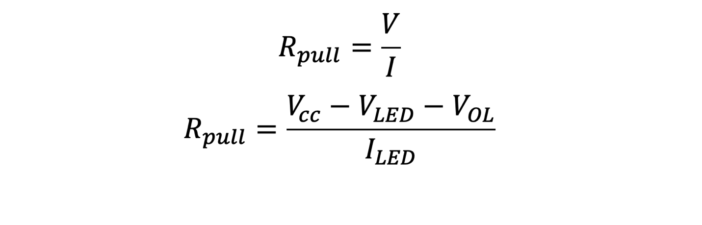
For pull-up resistors:

Modifying the equation by applying KVL as per the given configuration:

Conclusion
Pull-up and pull-down resistors are ordinary resistors used in conjunction with digital logic gates and microcontrollers that maintain a definite high and low input. They avoid any floating states at the inputs when input terminals do not have any external signals.