The circuits that are not purely resistive have inductances and capacitance as well, also they have reactive power along with real power. Therefore, to calculate the total power for such circuits, we need a power triangle.
Power Triangle in AC Circuits
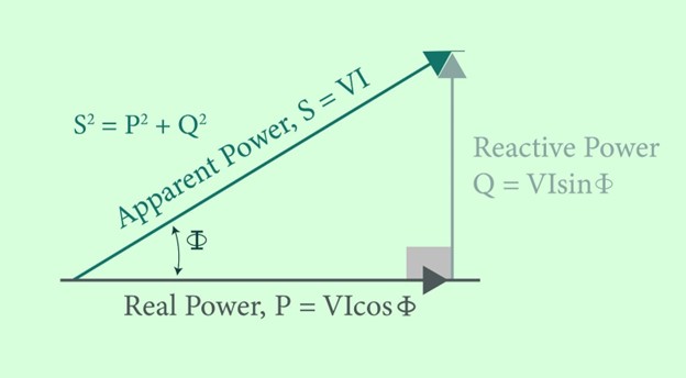
The total power in a circuit is the apparent power, and it is calculated from the vector sum of real and reactive power. The vector sum diagram that gives the sum of real and reactive power in an AC circuit is known as a power triangle. It becomes a right-angled triangle with real power as a base, reactive power as perpendicular and apparent power as hypotenuse, as shown in the figure below.
In the above diagram,
P = VI cos ϕ = I2R where R is the total resistance in the circuit. P denotes the real power which is consumed in the circuit.
Q = VI sin ϕ = I2X where X is the combined reactance of capacitors and inductors in the circuit. The product of the square of current and combined reactance is the reactive power that is Q.
S = VI = I2Z where the total impedance of the circuit is Z whereas S is the total or apparent power of the circuit.
According to Pythagoras’ Theorem:
So, we can use Pythagoras’ Theorem to calculate total power from the above-given power triangle. It will give:
Now, we need to know what active, reactive, and apparent power in a circuit is.
What is Active or Real Power
Real or active power is the useful work done in a circuit. Real power is the power that is consumed by the resistive elements of the circuit, and it is calculated or measured in Watts (W). The real power in AC circuits is similar to the power consumed in DC circuits.
Voltage and current do not have a phase difference when we talk about real power. It is because a resistor is a passive element and does not give voltage or current in circuits like capacitors and inductors.
What is Reactive Power
Reactive power is the power that is not used to perform any desired work in a circuit. It is also called wattless power or quadrature power because there is no actual power consumed in the circuit. The reactance of Inductors and capacitors is responsible for reactive power in an AC circuit. Reactive power does not exist in DC circuits.
The unit to determine the reactive power is Volt-Ampere-Reactive. Voltage and Current are not in phase with each other for reactive circuits. The reason for this difference is that the energy stored in capacitors and inductors tries to control voltage and current in the circuit. As a result, capacitors release reactive power in the circuit and inductors absorb it, but no actual work is done, and reactive power remains present in the circuit.
What is Apparent Power
As we know, resistors dissipate power, and reactive power is used by reactance in the circuit. There is no phase difference of voltage or current in resistive circuits; however, voltage and current have phase differences in reactive circuits. Therefore, apparent or complex power cannot be an algebraic sum of real and reactive power. To calculate the magnitude of apparent power, root mean squared values of voltage and current are simply multiplied, and its phasor orientation is determined by a vector sum diagram. The unit used to determine apparent power is Volt-Amperes.
Example of Power Triangle
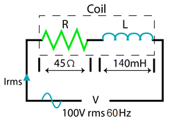
An inductive coil that has an inductance of 140mH and a resistance of 45 Ω is attached to a 100V rms 60 Hz supply. Calculate:
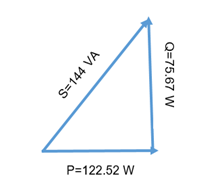
Also, draw the resulting power triangle for the given coil.
- The Impedance of the coil
- Current drawn by coil
- The power factor
- The Apparent Power, The Real Power, and The Reactive Power

Or
Power Triangle
Power Factor in AC Circuits
The power factor comes when real power is divided with apparent power. It can be calculated by taking the cosine of the angle that exists between voltage and current as well. Another way of defining the power factor is the ratio of resistance to impedance in the circuit.
In the circuits in which only resistive elements are present, the power factor is one and the angle is zero between voltage and current.
In the purely capacitive circuit, current leads voltage by 90°, so its power factor is leading for capacitors.
In the purely inductive circuit, current lags voltage by 90°, so its power factor is leading for inductors.
Power Factor is used to measure the energy efficiency of AC circuits. By calculating the ratio of real to apparent power, it determines how much actual power is consumed in a circuit. The table given below shows ranges of power factors that are considered good or bad.
| Power Factor | Range |
| Perfect | 1 |
| Good | 0.95 to 1 |
| Poor | 0.85 to 0.95 |
| Bad | 0.85 and below |
Why Do We Need to Improve the Power Factor
The power factor needs to be improved because if the power factor is below 0.85 a large amount of current is drawn from the source to do the same amount of work. This means the work done is the same, but the current drawn is increased. If the power factor is optimized, we can do the same work with less current drawn.
Hence, it increases the cost of electricity used, requires heavy installations, and damages source installations. That is why electric supply companies often charge penalties to industries that have very bad power factors.
How to Improve the Power Factor
To improve the lagging power factor, capacitors are introduced in circuits. This is because in capacitors current leads voltage which helps in realigning voltage and current and thus make the power factor approach approximately 1.
To correct the leading power factor in the case of highly capacitive loads, inductors are introduced in circuits. This is done because in inductors, current lags behind voltage. It helps to realign voltage and current and thus makes the power factor approaches approximately 1.
FAQs
Can the power factor be over 1
Power factor comes from the division of real and reactive power. As real power is a component of apparent power, it cannot be greater than apparent power. As a result, the power factor cannot be greater than 1.
Can the power factor be 2
The power factor can never be equal to 2 because it is a violation of the law of conservation of energy and real power cannot be double apparent power.
For which circuits power factor can be 1
The value of the power factor is equal to 1 for the circuits that only have resistances in them. It is because there is no reactive power in resistive circuits and the real power consumed by resistive elements is equal to the apparent power.
Can the Power Factor Be Negative
Yes, in exceptional conditions the power factor can become negative. A negative power factor means that current is flowing from load to source instead of source to load. However, it usually does not happen because it causes damage to the power supply.
Why power factor of 1 is needed
We want the power factor to be 1 to conserve energy. A power factor that is less than one indicates that power is reversed in the circuit and the load is supplying power to the circuit. However, a power factor of one indicates that no energy is lost in the circuit from source to load.
Conclusion
A Power Triangle and power factor are very important for the study and analysis of AC circuits. The power dissipated by the resistive load is real power, and the power due to capacitors and inductors is reactive. Reactive power is not utilized in the circuit. The total power or apparent power of a circuit is calculated through a power triangle, and the power factor determines how much an AC circuit is power efficient.


