What is Power Factor Correction?
Power factor correction is a method used in AC circuits to bring the power factor as close as possible to unity. It is done by adding the parallel capacitors to the circuit, which reduces the reactive power of the inductive circuits, resulting in the reduced load on supply.
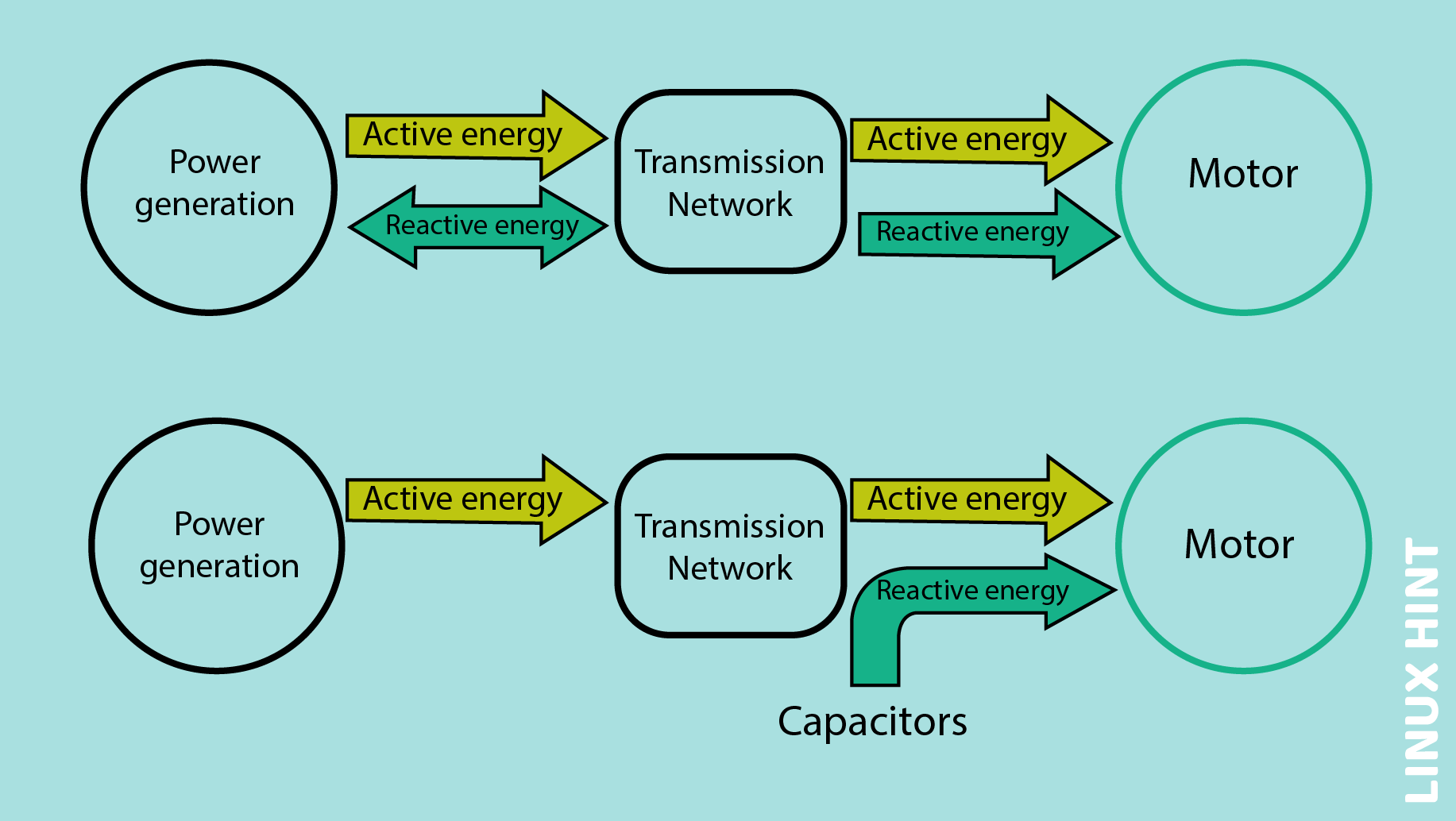
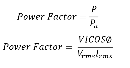
Power Factor in AC circuits refers to the ratio of the real power at the load to the apparent power which flows in the circuit. Apparent power is basically the product of RMS values of current and power. It is the measure of the maximum power that a system must be able to withstand. Its measuring units are volt-Amperes (VA). In AC circuits real power is the product of current and power at some instance, because both the current and power in an AC circuit are sinusoidal so with respect to the source frequency the direction and magnitude keep changing. It is the measure of the actual power consumed due to resistive load. Its measuring unit is Watts.
The equation for power factor is given as:
The Need of Power Factor Correction
Power factor is in general the measure of the efficiency of the power system. It can range from 0 to 1. Power factor less than 0.95 is referred to as poor, while when it ranges between 0.95-0.99 it is said to be good. When the power factor reaches 1 then it is approved to be perfect.
Low power factor means the system is inefficient. This inefficiency of the system leads to the drawing of more apparent power from the system. Low power factor demands more current for the same output power. The increased demand of current leads to increased losses in the system. To withstand these increased losses bigger systems and equipment will be required which makes the system costly and inefficient.
How To Implement Power Factor Correction Explained With an Example
When dealing with truly resistive loads the current and voltage are in phase hence, they have the unity power factor. While in case of linear circuits which consist of the combination of capacitors, resistors and inductors, they demonstrate the sinusoidal wave response to the sinusoidal line voltage. Due to the impact of inductance and capacitance, a linear load can change the phase, creating the phase angle of 90 degrees, current lagging behind the voltage. So, the presence of resistance and inductance combine to create the effect called impedance. It is measured in ohms, and is denoted by Z.
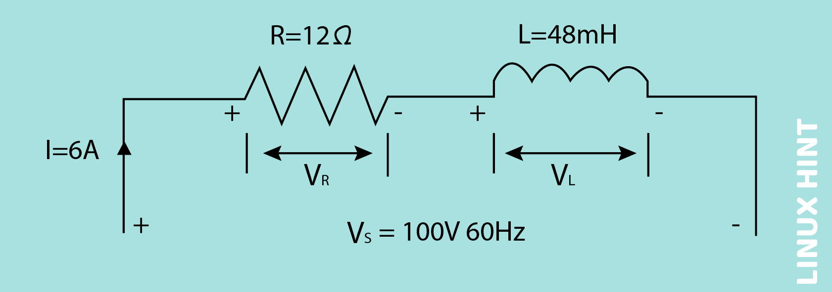
A coil has the resistance of 12 ohms and inductance of 48mH. When it is connected to the power supply of 100 Vrms and 60Hz, if 6 Amperes current is drawn by it, then calculate the following:
1) the voltages across the components of the circuit
2) the phase angle of the circuit
3) the different powers consumed by the series RL circuit
1: Find Impedance:
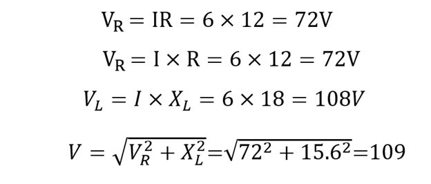
2: Voltages Across Resistor VR and Inductor VL:
3: Phase Angle of the Circuit:
4: To Calculate Power of the Circuit:
The RL series circuit under discussion consumes large apparent power because the current lags behind the voltage with a large angle which results in poor power factor, which is 0.6. So, to improve the power factor, some of the reactive power should be cancelled. The addition of a parallel capacitor will decrease the current demand and reactive power in the circuit. To add the capacitor, first we have to calculate the value of the required capacitor. As 0.95 is a good power factor, so to achieve this power factor for the circuit we need:
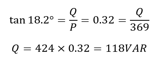
Hence, the amount of reactive power required is:
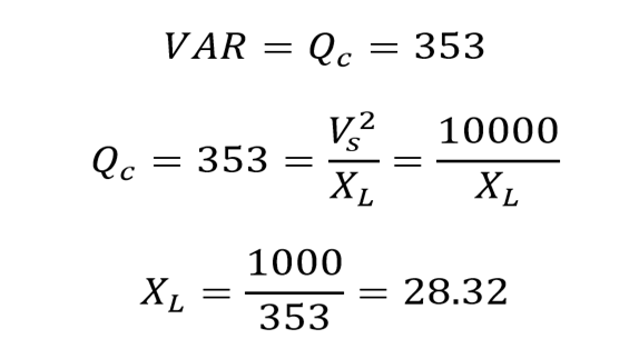
The 118 VAR reactive power is needed to for 18.2 phase angle. If the new calculated value for VAR is 118 VAR and the original value was 472 VAR, then we need 472-118= 353 VAR capacitive reduction. So:
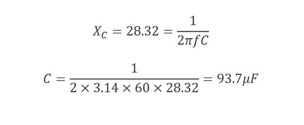
For the reduction of reactive power to the 118 VAR, the capacitive reactance of the capacitor must be 28.32 Ω at the standard frequency. Capacitance of the capacitor can be calculated as:
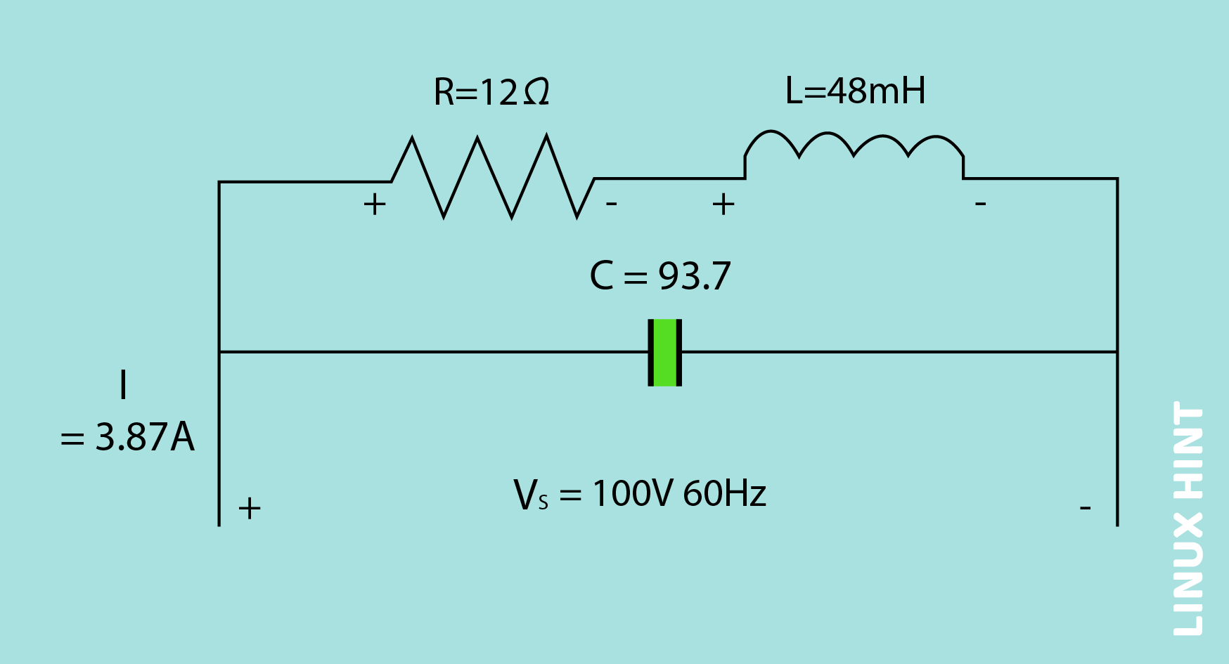
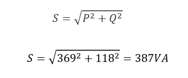
The parallel capacitor of 93.7µF is required to improve the power factor of the system under consideration from 0.6 to 0.95. After the application of power factor correction technique, the real power provided by the source can be calculated using the values given above as;
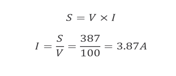
We can calculate the RMS value of the current, if the apparent power of the circuit is reduced from 600VA to 387VA as following:
Hence, by using a capacitor in parallel combination, the power factor is improved to 0.95 and the demand of current is reduced from 6A to 3.87A, which is a quite noticeable and impactful difference.
Conclusion
The power factor correction technique is used to improve the efficiency of the system. It reduces the apparent power as well as the current demand for the electrical system, hence making the system cost and application efficient.

