The unit that we can use to measure the potential difference across any point is called a Volt. A volt is a potential difference applied across the resistance of 1 ohm, and it will result in the flow of electric current from the higher terminal to the lower terminal.
Potential differences always flow from higher potential value to lower potential value. We can also define the 1V as the potential when 1 Ampere of current is multiplied by the 1 ohm of resistance. To describe the potential difference, the ohm law formula is used, which is equal to V=IxR.
According to Ohm’s Law, current in linear circuits increases with the increase in potential difference. A circuit having a large potential difference between any two points will result in a more current flow across these two points in a circuit.
For example, consider a 10 Ω resistor, and the voltage applied across its one end is 8V. Similarly, the voltage across its other end is 5V. So we will get a 3V (8V-5V) potential difference on the resistor terminal. To find the current across the resistor, we can use the Ohm law. The current of this circuit would be 0.3A.
If we increase the voltage from 8V to 40V, the resistor potential difference will become 40V – 5V = 35V. This will result in 3.5A of the current flow. When the difference of potential across the resistor increases, it will also result in an increase of current.
To measure the voltage of any point inside a circuit, we have to compare it with the common reference point. We normally use the 0V or ground pin as a reference point in the circuit for measuring the potential difference.
Quick Outline
- What is the Potential Difference
- Potential Difference Example
- Voltage Divider Network
- Voltage Divider Formula
- Voltage Divider Example
- Conclusion
What is the Potential Difference
The potential difference, also known as voltage, is a core concept in electricity. It basically describes the difference in electric potential energy between two points within an electrical circuit. The difference in potential between two points causes the charge to move from a higher to a lower potential point. This will result in the flow of electric current. We measure the potential difference in volts (V), and it’s a critical factor in determining how electricity behaves in a circuit and how electrical devices operate.
Potential Difference Example
In the image, the potential applied across the resistor at one end is 10 V. The potential on the second end of the resistor is 5 V.

To calculate the potential difference across the end of the resistor, subtract the higher potential from the lower:
![]()
The potential difference calculated across the resistor is 5V.
The current in the resistor is proportional to the applied potential. If the potential difference between any two points is greater, you will see a large current flow.
Use Ohm’s law to find current.
![]()
![]()

Now, increase the potential from 10V to 20V across one end of the resistor and 5V to 10V across the other end. The difference of potential will become 10 V. Using the Ohm law you can find the current through the resistor which is 8 amperes.

Electric charge causes the electric current to flow. But the potential doesn’t physically move or flow. The potential is applied across any two specific points in the circuit.
To find the total circuit voltage, we have to add up the all connected voltages in the series circuit. This means that when you have resistors (V1, V2, and V3) connected in series, you simply sum their voltages to find the total voltage:
![]()
On the other hand, when you connect resistors in parallel, the voltage across each resistor or element remains the same. In parallel, the voltage across each resistor is equal, and it can be expressed as:
![]()
Voltage Divider Network
We know that if we connect multiple resistors in series across a potential difference, a new voltage divider circuit will form. This circuit divides the supply voltage among the resistors in a specific ratio. Each resistor gets a portion of the voltage relative to its resistance.
This voltage divider circuit principle only applies to resistors that are connected in series. If we connect the resistors in parallel, it will result in a completely different setup, which is called a current divider network.
Voltage Division

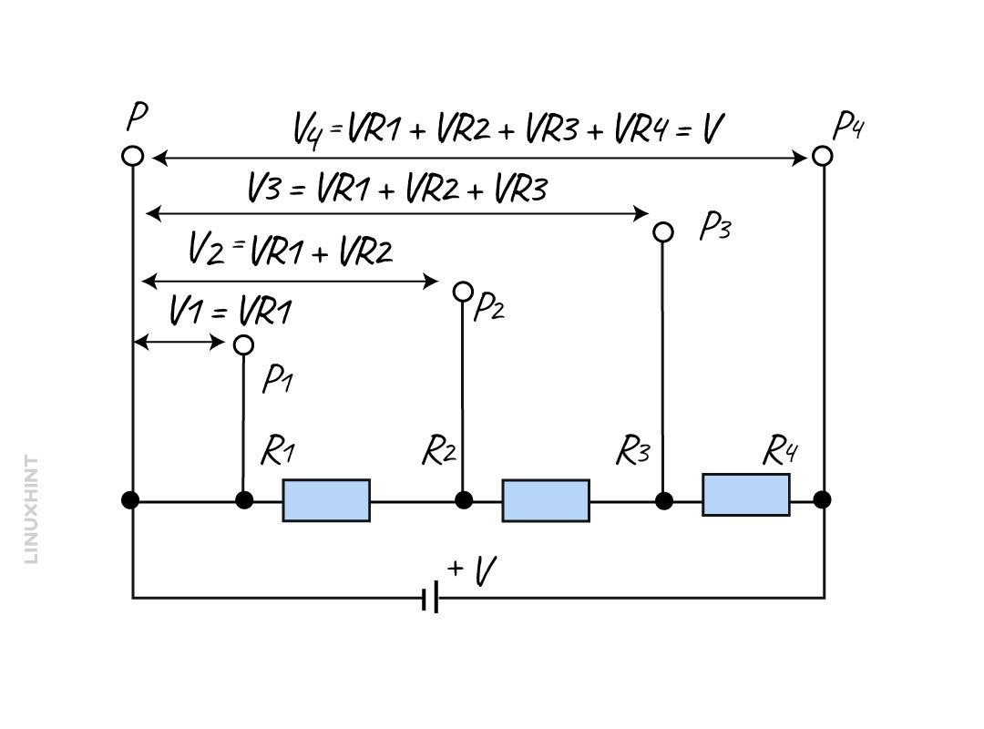
The given circuit explains the fundamental concept of a voltage divider circuit. In this circuit, different resistors are in series. There are 4 resistors in series named R1, R2, R3, and R4. All these resistors share a common reference point which is equal to zero volts or ground.
When you connect resistors in series, the supply voltage (VS) is distributed across each resistor. You will see each resistor will drop some voltages. This means that each resistor gets a share of the total voltage.
Next, use the Ohm’s Law to express this circuit. According to the definition of Ohm law, the current (I) flowing through a series of resistors is equal to the supply voltage (VS) divided by the total resistance (RT).
Ohm law mathematical expression is given as

Now use Ohm law and simply multiply the current (I) with the resistance (R) value of each resistor.
![]()
Where V represents the voltage drop.
After moving from one point to another along the series of resistors, the voltage at each point increases as you sum up the voltage drops. All individual voltage drop sums are equal to the circuit input voltage (VS).
It’s not necessary to find the total circuit current in order to find the voltage at a specific point. You can use a simple formula to calculate the voltage drop at any point by considering the resistance of the resistor and the current flowing through it. This simplifies the analysis of the circuit and helps in understanding how the voltage is distributed within the circuit.
Voltage Divider Formula

In the above formula, V(x) represents the voltage, and R(x) is equal to the resistance produced by this voltage. Symbol RT denotes the total series resistance of the resistors and VS is the supply voltage.
Voltage Divider Formula
Consider the below circuit to find the output voltage of the circuit across R2 using the voltage divider rule.
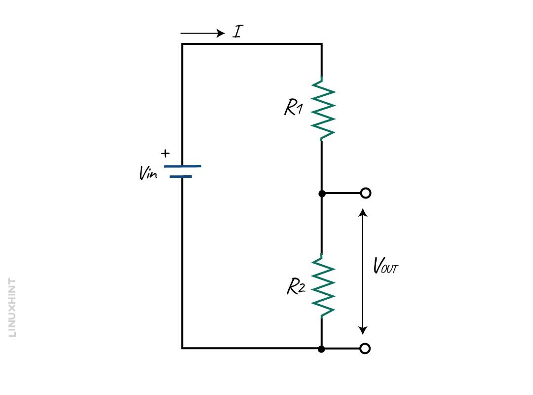
In this circuit, the Vin denotes the supply voltage. It is the current flowing through the circuit. This current flows in both directions.
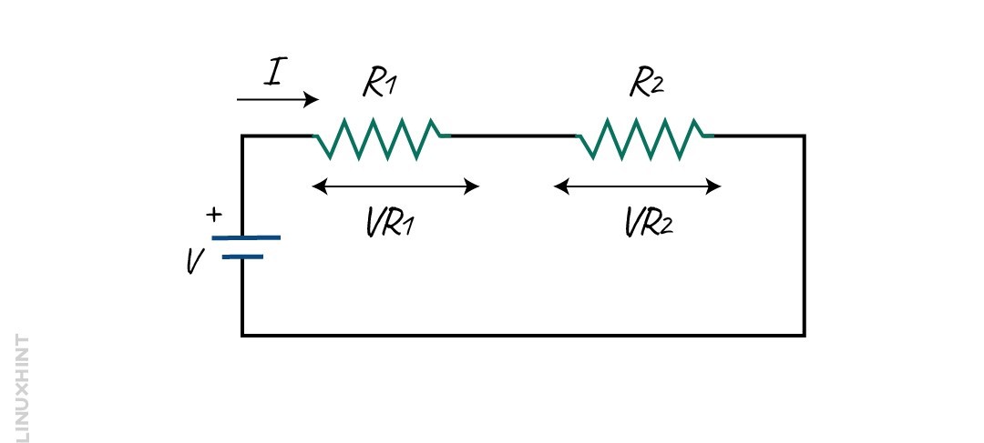
Let’s consider VR1 and VR2 to be the voltage drop of R1 and R2. As the given resistors are connected in series, the input voltage VIN of the circuit will be equal to the sum of all individual voltage that is dropped against each resistor.
![]()
To calculate the individual voltage drop across each resistor, use the Ohm law equation:
![]()
Similarly, for the resistor R2
![]()
From the image, we can see that the voltage across R2 is VOUT. This output voltage can be given as:
![]()
From the above equation, we can calculate the input voltage VIN.
![]()
![]()
To calculate the total current in terms of Vout voltage, use the above Vout equation.

So the Vout equation will become:

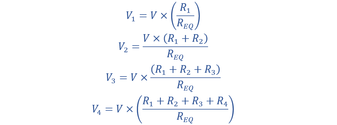
Now consider a multiple voltage divider circuit that contains multiple outputs across the resistors.
The output equation will become:

Here, in the above equation, the VX is the output voltage.
RX is the sum of all resistors connected in the circuit.
The possible values of RX are:

If V stands for the supply voltage. Then the possible output voltages are given as:
From the above equations, we can conclude that the voltage dropped across the resistors which are connected in series is proportional to the value or magnitude of the resistor. According to Kirchhoff’s voltage law, the voltage dropped across all given resistors must be equal to the source input voltage.
So you can find the voltage drop of resistors using the voltage divider formula.
Voltage Divider Example
Consider a Voltage divider circuit with three resistors in series, producing two output voltages from a 240 V supply. The resistance values are as follows:
- R1 = 10 Ω
- R2 = 20 Ω
- R3 = 30 Ω
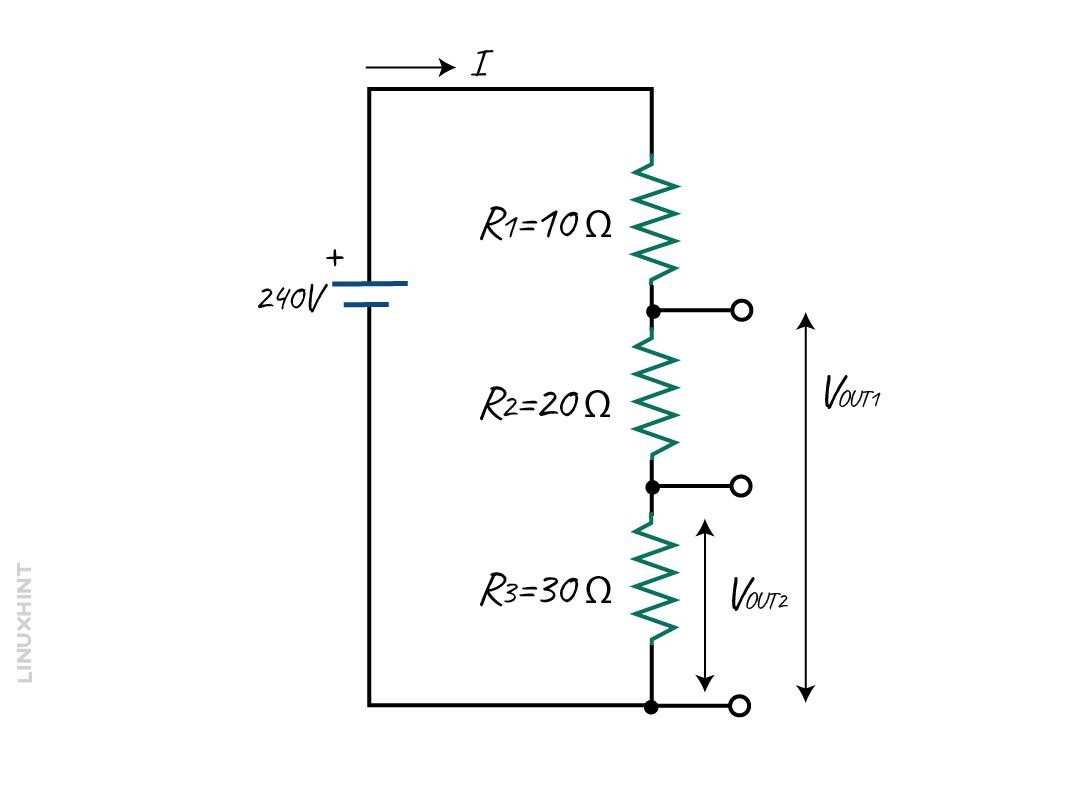
The equivalent resistance of the circuit is calculated as:

Now, the two output voltages are determined as follows:


The current in the circuit is given by:

Therefore, the voltage drops across each resistor are as follows:

Conclusion
A voltage divider is a fundamental passive circuit used in electronics. This circuit can reduce the output voltage relative to the input voltage. You can achieve this reduction in voltage after connecting multiple resistances in series. The value of resistance depends upon the voltage drop value you want to achieve. These resistors will create a fixed voltage fraction determined by the resistor ratios.
Resistors are important circuit elements as they can limit the voltage of the circuit according to Ohm’s Law. Resistors in series have a constant current through each resistor. You can calculate and maintain a constant voltage while designing electronic circuits with the help of a voltage divider formula.