Passive Band Pass Filter
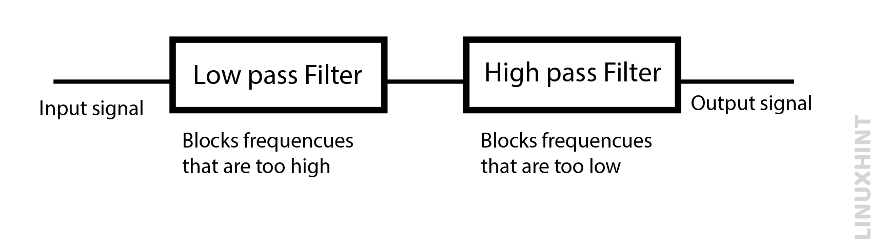
A band pass filter segregates a specific range of frequencies from others within a particular frequency group. Some sophisticated electrical circuits may not find it suitable to allow very low frequencies at 0Hz or very high frequencies to pass through them, the passive band pass filter does the frequency selectivity functions depending upon series resistor and capacitor combinations in their circuit. They block both the lower frequencies and upper frequencies outside their selective bandpass range. These filters are composed of a low pass and high pass filters.
Construction
A typical band pass filter shall present two RC networks as shown below:
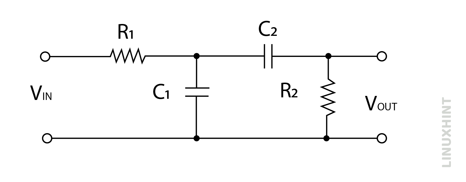
One RC network is used in series, while the other RC network is used in parallel. The cut-off frequency values can be controlled through resistor and capacitor values used in the band pass filter circuit. It can allow a wide range of frequencies or a narrow range of frequencies, depending upon the cut-off frequency values. Therefore, a specific range of bandpass frequencies is called bandwidth.
Frequency Response Curve
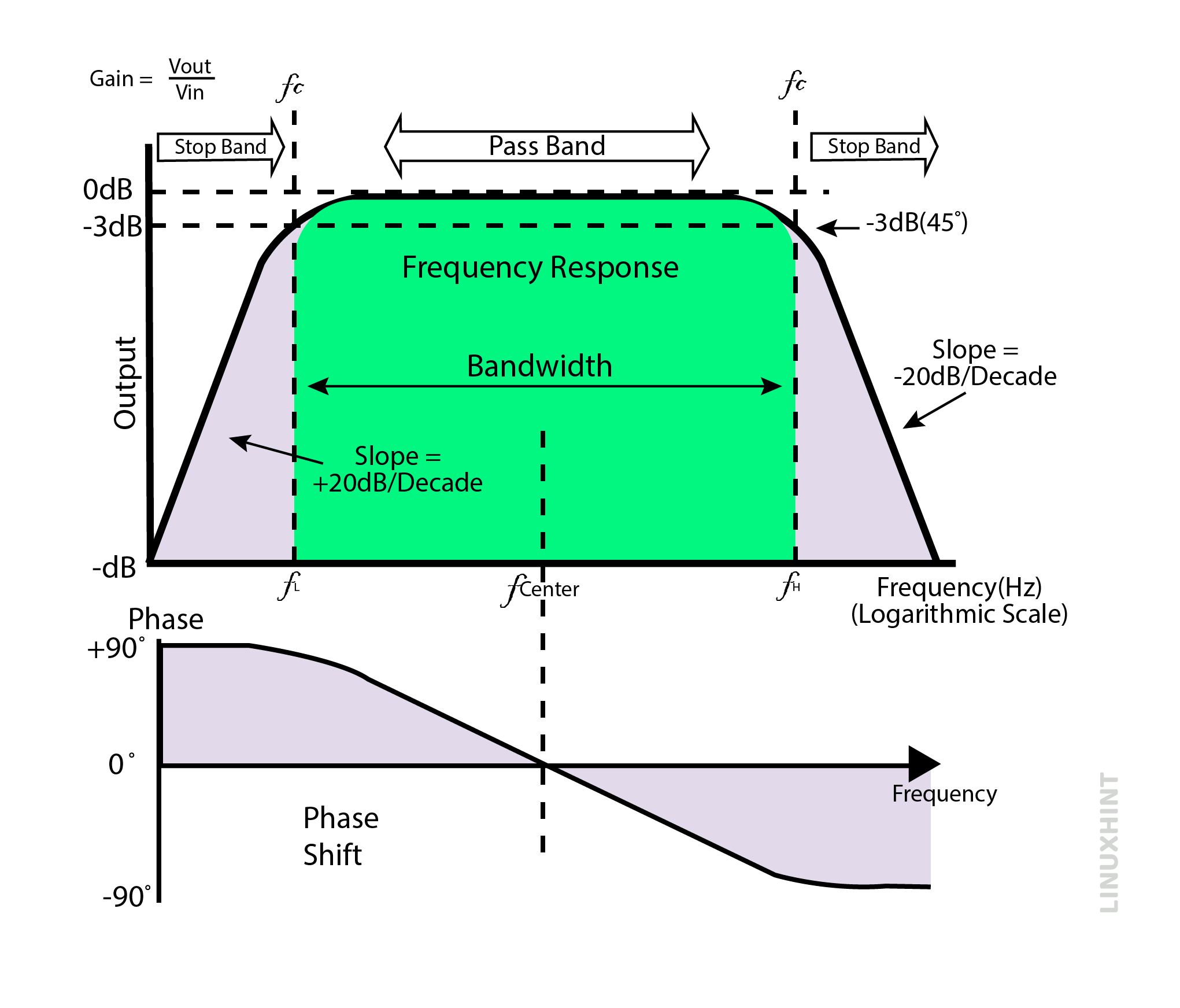
The frequency response curve is shown below. The frequency response curve shows two cut-off frequency limits: lower cut-off frequency limit fL and high cut-off frequency limit fH. All frequencies below lower cut-off frequency fL are blocked until the output of the band pass filter rises at the slope of 20db/decade. The output then reaches a maximum value of 70.7% and remains constant for a specific range of frequencies until the higher frequency limit of fH is reached. The output starts to fall again at a slope of -20db/decade.
The maximum gain of -3db has been denoted both in rising trend and falling trend in the below figure. Therefore, the geometric mean of these two frequency points provides the resonance point or center frequency point.
Resonance Frequency
The geometric mean of upper cut off-frequency and lower cut off-frequency is expressed as:

fr presents center frequency, while fh presents upper cut off-frequency value and fl stands for lower cut off-frequency value.
Phase Shift
Band pass filters are second order filters. It means presence of two passive element combinations in its circuit. The phase angle for second order filters will be twice the phase angle of the first order filters. It means that the phase angle shall be 180 degrees in the band pass filter. The phase shift indicated +90 degrees up to center frequency and -90 degrees after the center frequency point.
Upper & Lower Cut-off Frequencies
The upper & lower frequency values can be calculated just like the frequency calculations in low and high band pass filters. The general expression is given by:

Example:
A band pass filter is to be designed that allows frequencies between 5kHz and 40kHz. Assuming resistors are 20kΩ, calculate capacitor values and draw the final band pass filter.
Using general expression of upper and lower cut-off frequency:

The high pass capacitor value can be calculated using lower frequency limit:

The low pass capacitor value can be calculated using higher frequency limit:


Conclusion
Band pass filters work on the principle of passing a selective range of frequencies while blocking all lower or higher ones. They are composed of both of the low pass filter and high pass filter networks in their construction.