What is Norton’s Theorem
This theorem is a technique used to analyze and simplify electrical circuits containing multiple interconnected elements such as resistors, capacitors, and inductors. Norton’s Theorem allows us to replace any network of linear passive elements connected to a specific load with an equivalent current source and a resistor in parallel.
Procedure of Norton’s Theorem
To apply Norton’s Theorem, the following steps are typically followed:
Step 1: Determine the Norton Current
Connect a short circuit (a wire) across the load’s two terminals in the original circuit in order to calculate the Norton current (In). Measure the current flowing through this short circuit, which represents the Norton current.
Step 2: Disable all Independent Sources.
Next, disconnect all independent sources in the circuit, including voltage sources and current sources. Independent sources are those whose values do not depend on the circuit variables.
Step 3: Find the Norton Equivalent Resistance
Next, find the Norton equivalent resistance (Rn) by removing the load from the original circuit. The resistance measured from the terminals where the load was connected should be calculated after any voltage sources have been replaced with short circuits and any current sources have been replaced with open circuits. This value represents the Norton equivalent resistance.
Step 4: Create the Norton Equivalent Circuit
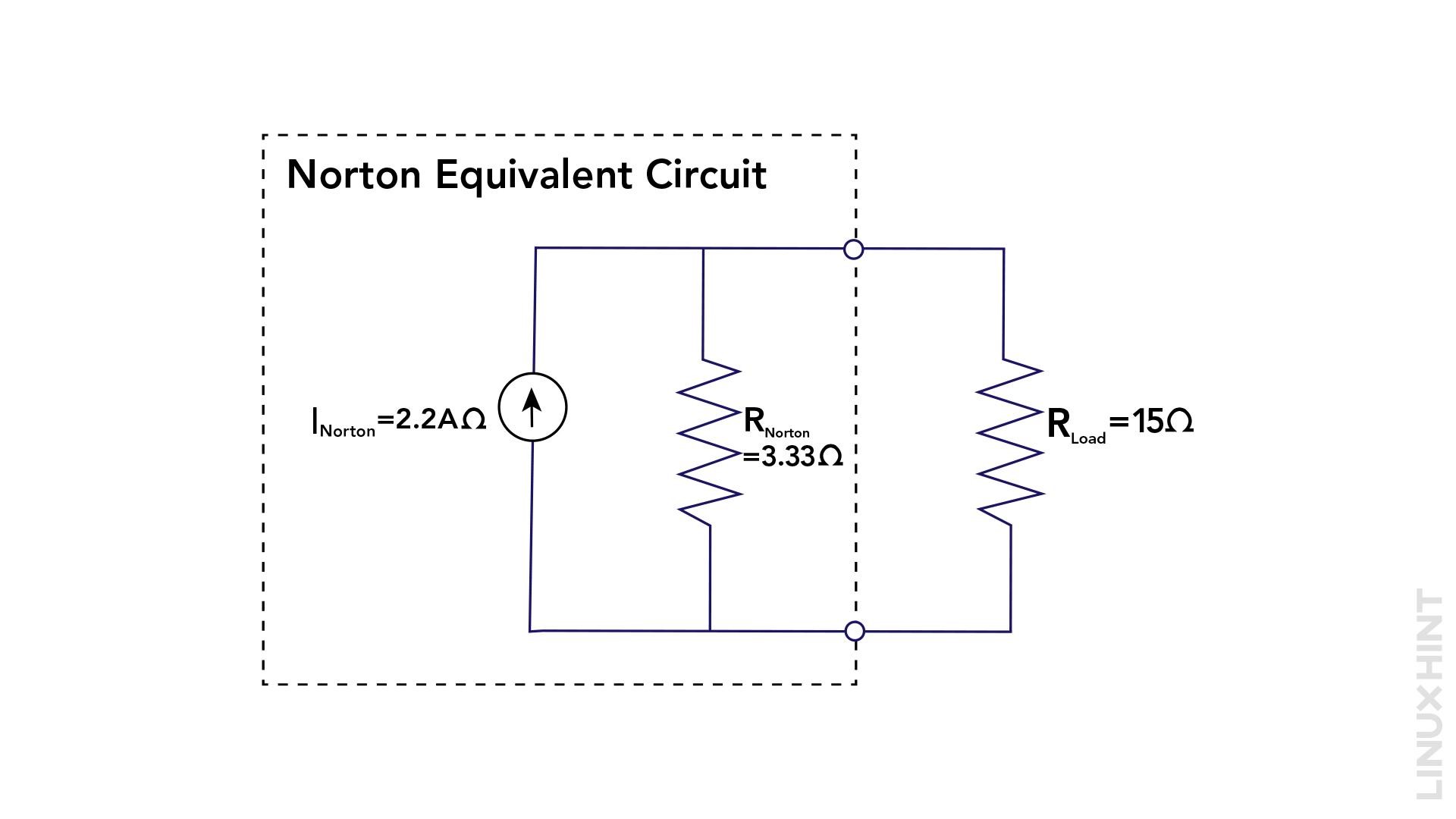
Once the Norton current (In) and Norton equivalent resistance (Rn) are determined, construct the Norton equivalent circuit. This involves connecting an ideal current source (with value In) in parallel with the Norton equivalent resistance (Rn).
Example
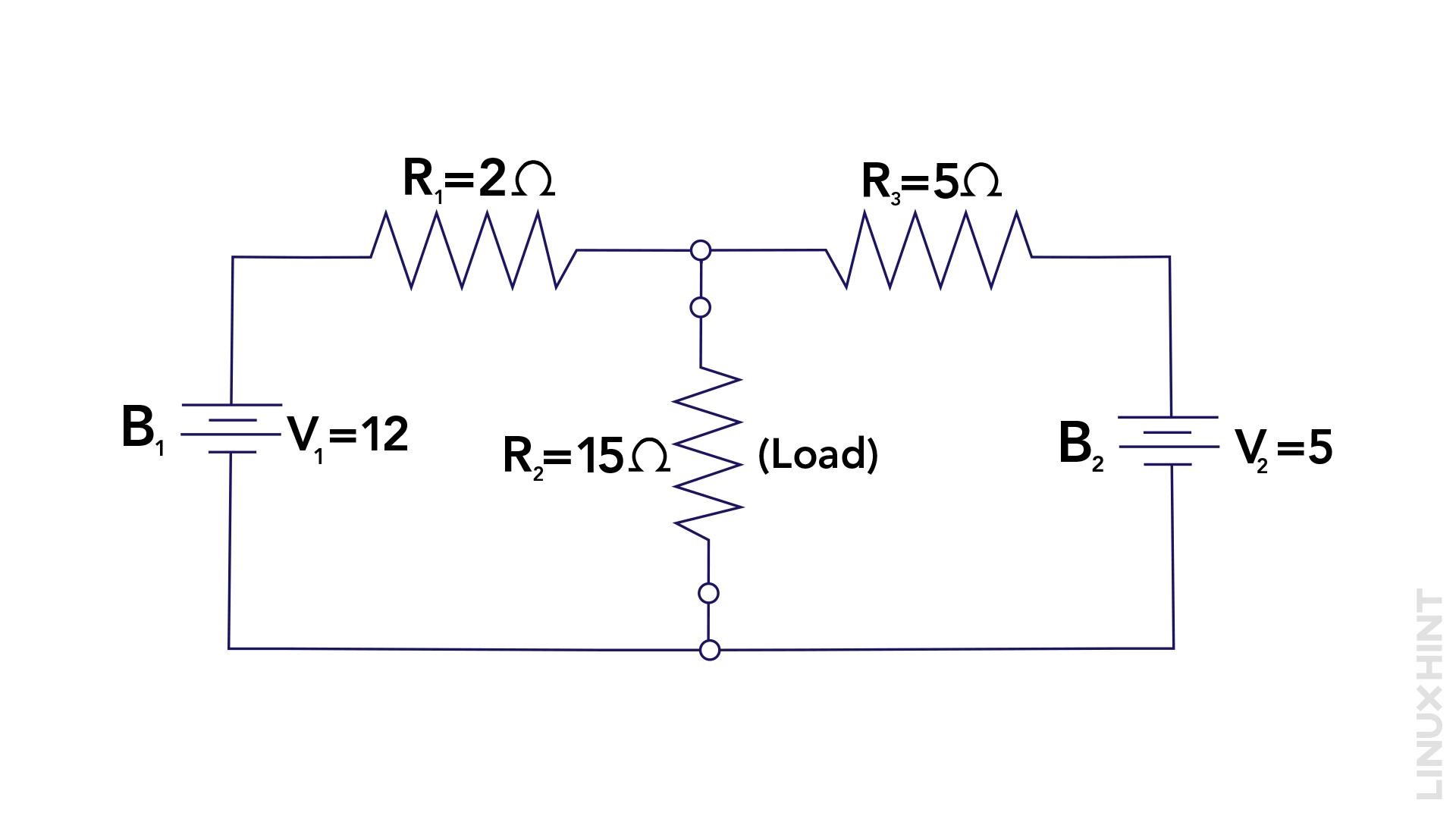
Here is a simple circuit as an example to demonstrate Norton’s Theorem. The circuit consists of a 10-ohm resistor (R1) and a 5-ohm resistor (R3) in parallel, connected to a 12V and 5V voltage sources (V). The load resistor (R2) is connected between the two resistors R1 and R2 having a value of 15 ohms:
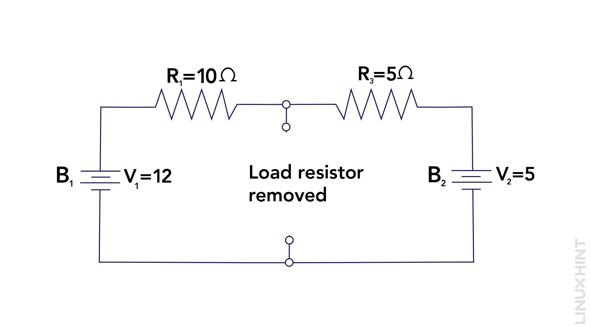
1: Remove the Load Resistance to Determine the Norton Current
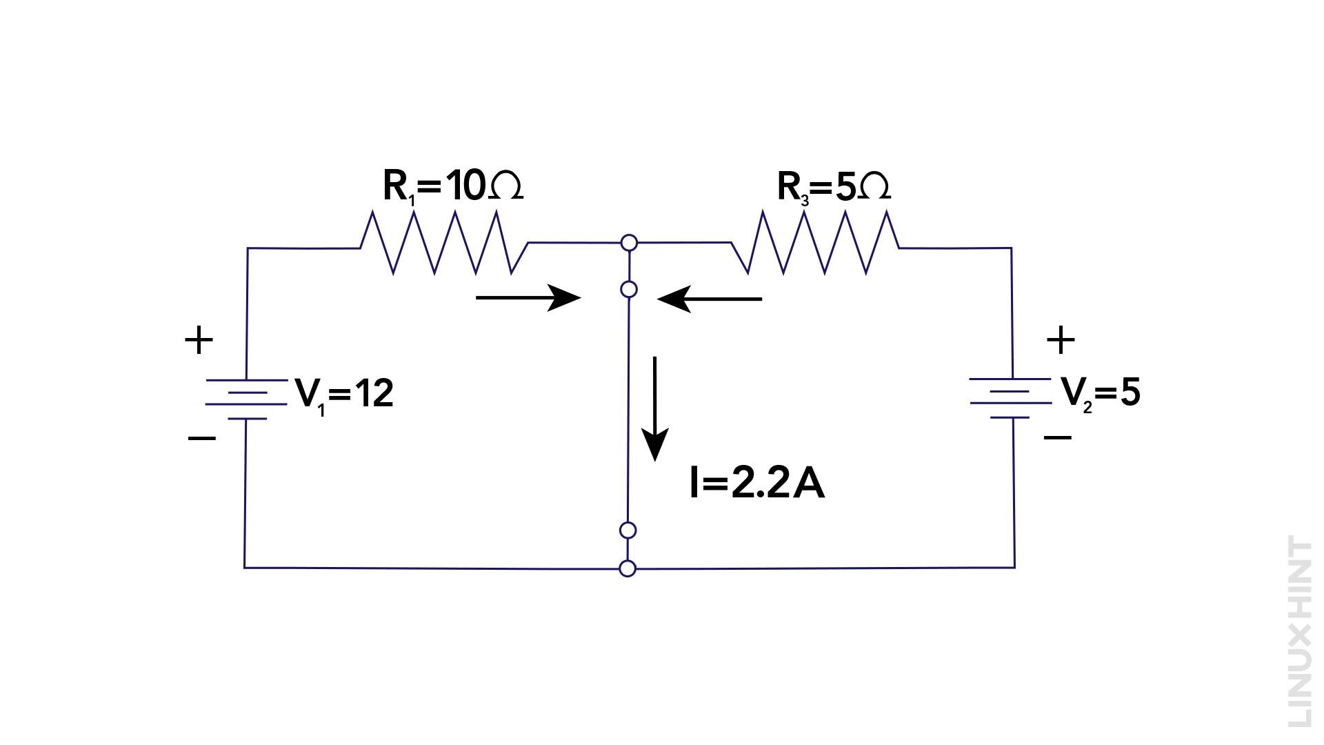
Connect a short circuit across the terminals of load resistance (RL) and then measure the Norton current (IN) using the following equation:
Now by putting the values of current using Ohm’s law, find the Norton current:
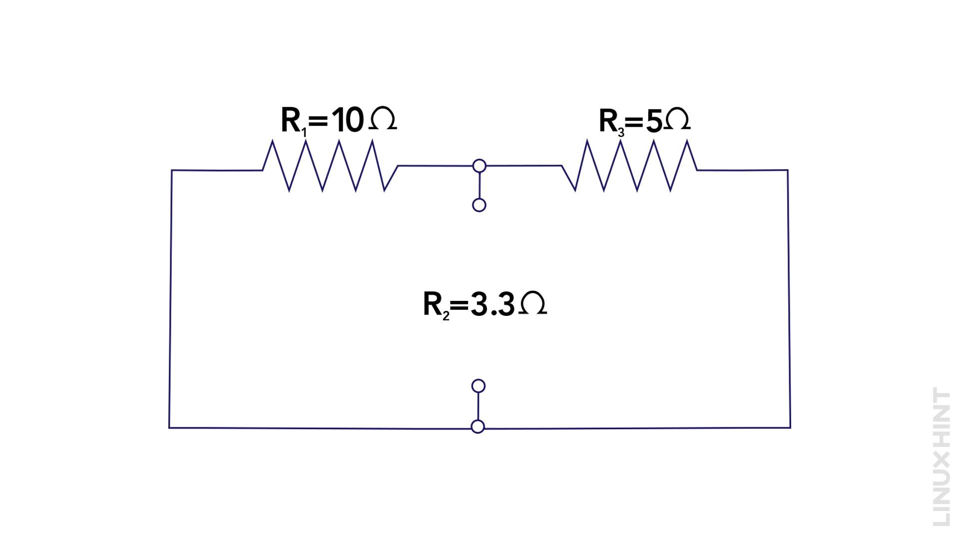
2: Disable all Independent Sources and Find the Norton Equivalent Resistance
Remove the 12V and 5V voltage sources (V) and find the equivalent resistance. In this case, R1 and R3 are in parallel, so the total resistance can be calculated using:
3: Create the Norton Equivalent Circuit
Construct the Norton equivalent circuit by connecting a 2.2A current source in parallel with a 3.33-ohm resistor and a load resistance of 15 ohms.
Now to calculate the voltage drop across the load resistance, first find the equivalent resistance:
Now calculating voltage across the load resistor using:
Now calculate the current flowing in the load resistance using:
Conclusion
Norton’s Theorem is a valuable tool in circuit analysis and design, enabling engineers to simplify complex circuits into simpler, equivalent forms. By following the step-by-step procedure discussed above, one can efficiently apply Norton’s theorem to analyze circuits and determine their equivalent current source and resistance.

