An amplifier is an electronic device that is used to amplify or enhance the voltage or power of a signal so that it can be easily transmitted over long distances without losses. Therefore, they are used in wireless communication systems and broadcasting networks. Non-inverting amplifiers are those that give the amplified signal as output that is in the same phase as that of the input signal. This tutorial will explain the configuration, circuit diagram, and working of non-inverting operational amplifiers.
What is a Non-Inverting Operational Amplifier?
An operational amplifier has two inputs and one output and works as a differential amplifier by comparing input and output. A non-inverting operational amplifier gives an amplified output signal that is in phase with the input when the input is applied on the positive terminal of the op-amp.
Circuit Diagram of Non-Inverting Operational Amplifier
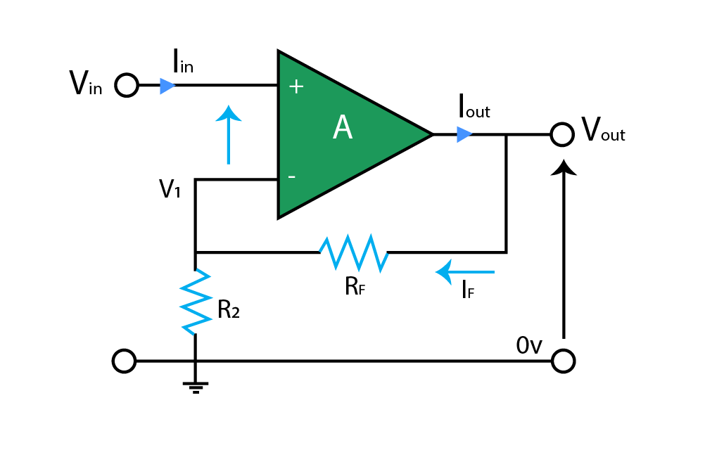
Given above is the circuit diagram of a non-inverting operational amplifier. Input voltage is applied on the positive terminal of the op-amp. The negative terminal of the op-amp is fed with the feedback of output through resistor RF, and it is also grounded through resistor R2. The output is taken from the output terminal with respect to the ground.
Working of Non-Inverting Operational Amplifier
A non-inverting operational amplifier uses output feedback at its negative terminal; therefore, it works as a voltage follower. By working as a voltage follower, it does not give an output signal at once but before giving an output signal it sends a portion of the output signal as feedback. The amplifier then differentiates the two inputs and amplifies their difference. This amplifier gives a non-inverted output signal that is in phase with the input, whereas its opposite is an inverting amplifier that gives an inverted and out-of-phase output signal.
Gain of Non-Inverting Operational Amplifier
The gain of an op-amp describes how much an amplifier has amplified the input signal. It is usually expressed by the division of the output voltage to the input voltage. The unit of expressing gain is usually decibels (dB). Following is the calculation of the gain of the non-inverting operational amplifier:

Here, V1 is equal to Vin:

Therefore, the voltage gain will be:

Voltage Follower as Unity Gain Buffer
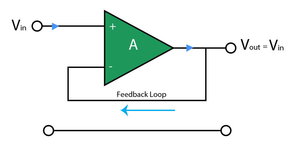
A non-inverting operational amplifier can also work as a unity gain buffer, in which the gain of the amplifier is 1. If feedback resistance is reduced to zero and input resistance is increased such that it approaches infinity, then the gain obtained would be fixed and equal to 1.
As feedback resistance is null, then all the output signal is feedback to the inverting input terminal and feedback is 100%. This will make VIN equal to VOUT. This configuration is known as “unity gain buffer” whose circuit diagram is given below.
The gain of this amplifier is given in two forms:
1. Using VIN equal to VOUT:

2. Using R2 is infinity and RF is zero:

The main benefit of such unity gain amplifiers is that it has high input impedance and low output impedance, so they can be used when it is required that the output signal of an operational amplifier should remain unaffected by changes in load impedance.
Example of Non-Inverting Operational Amplifier
Calculate:
- Gain of the amplifier
- Output voltage
- Current passing through the load resistor
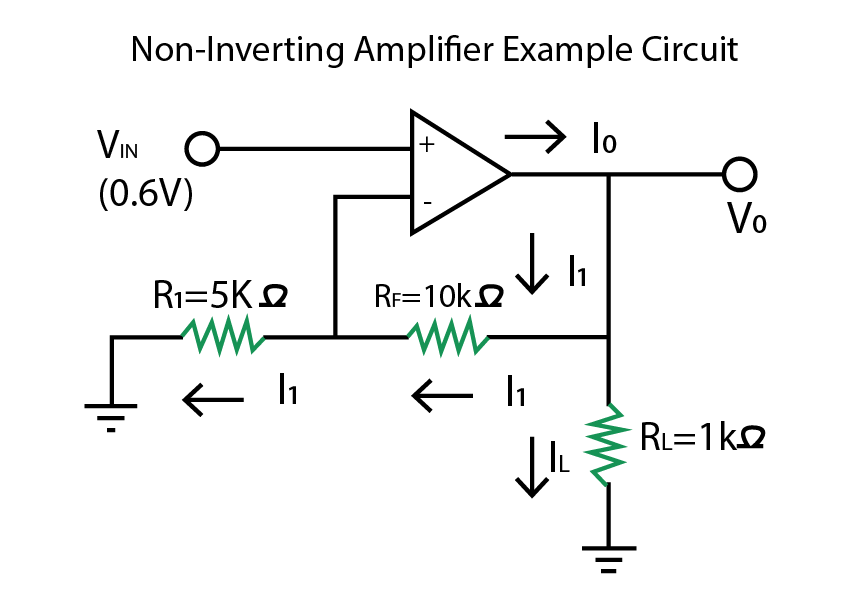
In the above-mentioned circuit, a non-inverting operational amplifier is given with a load resistance of 1 kΩ and VIN = 0.6V. We have to calculate gain, output voltage, and current through load resistance.
1. The Gain of Amplifier

2. Output voltage

3. Current passing through the load resistor IL

Conclusion
A non-inverting operational amplifier is a very beneficial electronic device that has a voltage gain of one or more than one. The amplification or gain is dependent on the resistors used in the circuit, so its gain can be adjusted by changing the values of resistors. Another benefit is that it gives a non-inverted output signal through the feedback process. It has wide applications in the field of wireless communication and technology.