The feedback system has multiple advantages over conventional systems. It helps to improve the output gain of the circuit and increases the linear response of the circuit. It also reduces the chances of signal distortions that occur mainly due to noise signals.
Feedback systems are mostly used in amplifier circuits, output-based control systems, and oscillator circuits. Feedback systems have two types: Positive feedback and Negative feedback. This article will focus much on the latter type of feedback.
Quick Outline:
- What is Negative Feedback System in Electronics
- Negative Feedback Circuit
- Negative Feedback Transfer Function
- Negative Feedback in Operational Amplifiers
- Example 1
- Example 2
- Example 3
- Difference Between Positive and Negative Feedback Systems
- Applications and Properties of Negative Feedback System
- Effect of Negative Feedback on Bandwidth
- Conclusion
What is Negative Feedback System in Electronics
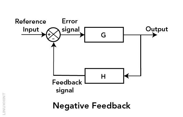
Negative feedback in an electrical circuit is a control mechanism that stabilizes and regulates the electrical circuit operations. Circuits with integrated negative feedback systems take an output signal and give it to the input as a phase opposition (inverted) signal. This feedback system reduces any deviations or errors in the output signals.
Negative feedback is also termed degenerative feedback. In negative feedback, the output signal coming as feedback is subtracted from the input reference signal. The output results in an error known as feedback gain. This error signal generated after subtraction will modify the system response accordingly. If the gain of the system is positive, the feedback signal coming from the output must be subtracted from the input reference signal to maintain the feedback as negative.
When negative feedback is subtracted from the reference input, it makes the system more stable. Let’s say there is a system that shows unusual behavior—to counter this change, the system will generate an output signal. This output or feedback signal counteracts the input signal—modifying the input accordingly to make the overall system run efficiently.
Negative Feedback Circuit
The negative feedback circuit is illustrated in the image below. Here you can see an output signal is taken back to the input side as feedback. On the input side, a difference between the reference signal and feedback signal difference is generated, which then drives the system further.
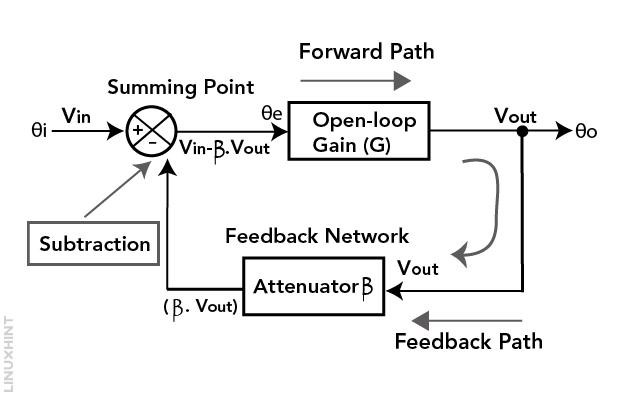
1. Components: The circuit consists of two main components:
- An amplifier with gain G.
- A feedback loop with feedback factor β.
The input signal is Vin and the output of the amplifier is Vout.
2. Summing Junction: At the input of the amplifier, there’s a summing junction (often represented by a circle with a minus sign inside). This junction will subtract the feedback signal from the reference input. The subtracted portion is the product of the feedback factor β and the output Vout—so the error signal is Vin – βVout.
3. Feedback Loop: This error signal (Vin – βVout) is what drives the system. It represents the difference between the desired input Vin and the actual output Vout scaled by the feedback factor β.
4. Negative Feedback: The key concept here is negative feedback. When the output Vout changes due to any disturbances or changes in the input Vin the error signal (Vin – βVout) is created. The calculated error signal will be amplified by the amplifier with gain G and fed back into the summing junction. Importantly, this feedback is negative because it is subtracted from the input.
- If the Vout increases (i.e. the system output goes higher than desired) the feedback reduces the error bringing Vout back towards the desired value.
- If the Vout decreases (i.e. the system output goes lower than desired) the feedback increases the error driving Vout back up towards the desired value.
5. General Feedback Equation: The general feedback equation for this system is typically expressed as
![]()
This equation relates the output Vout to the input Vin and the feedback factor β through the amplifier gain G. It shows how the system uses negative feedback to regulate and control the output to match the desired input.
Negative Feedback Transfer Function
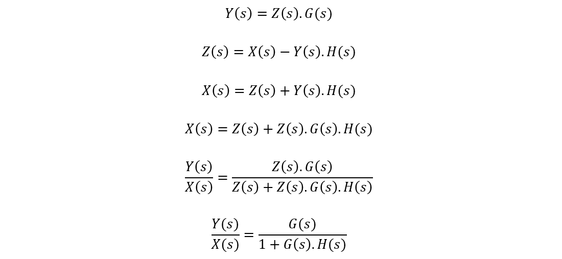
The transfer function defines an equation that represents the relationship between both input and output. It tells us how changes in the input affect the output. In negative feedback, we have an intermediate signal represented by Z. This intermediate signal represents the difference between the output and input.
For the transfer function equation of negative feedback, Z is used to calculate the error signal or correction needed to bring the system closer to the desired value of output.
The following block diagram shows the negative feedback system. Using this diagram, we can calculate the transfer function for a negative feedback system:
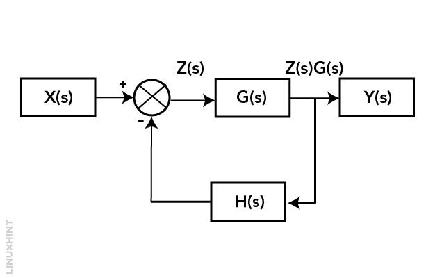
The output of the negative feedback system is equal to the Y(s):
Negative Feedback in Operational Amplifiers
In a negative feedback configuration, a portion of the op-amp’s output (V) is given to the input inverting (-) terminal. This output signal will be subtracted from the input reference. It helps to control and stabilize the amplifier’s gain.
Using negative feedback in an op-amp circuit, you can set the desired gain level while maintaining the system’s stability. Negative feedback reduces nonlinearities in the op-amp’s characteristics, making it operate closer to ideal behavior.
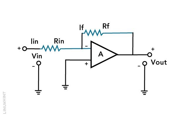
A negative feedback operational amplifier (op-amp) circuit is designed by using an op-amp as the central component. An op-amp has two inputs: one is inverting (-), and the other one is non-inverting (+). It has one output terminal. For the negative feedback system, we will be using the inverting side of op-amps.
This circuit typically includes:
- Input resistor (Rin) connecting the single source to the inverting (-) input of the op-amp.
- A feedback resistor (Rf) connecting the op-amp’s output to the inverting (-) input.
- A connection to the load at the op-amp’s output.
You can find gain by using the Rf to Rin ratio. This negative feedback stabilizes and controls the op-amp’s behavior. It works by minimizing the difference of voltages between the two inverting and non-inverting inputs. It creates a virtual short circuit between them. As a result, the op-amp adjusts its output voltage to maintain this balance—making it an effective amplifier with controlled gain.
Example 1: Calculating Closed Loop Gain
A system has a gain of 60 dB without feedback. The negative feedback fraction is 1/20th, find closed loop gain (in dB) with the addition of negative feedback.
Solution:
The closed-loop gain with negative feedback is given by the formula:

In this case, the open-loop gain is 60 dB, and the feedback fraction is 1/20.

So, with a feedback fraction of 1/20, the closed-loop gain of the system will be 86.02 dB.
Example 2: Calculating Voltage Gain
If an amplifier initially has a voltage gain of 3000 (without feedback) and then comprises a negative voltage feedback with a feedback fraction of mv = 0.01. What will be the new voltage gain of the amplifier?
Solution:
You can use the formula of voltage gain for the amplifier with negative voltage feedback—to calculate the voltage gain of the amplifier:

In the above formula:
Af = Voltage gain with feedback
A = Voltage gain without feedback
mv = Feedback fraction
Here we have:
Voltage gain without feedback (A) = 3000
Feedback fraction (mv) = 0.01
Now, put these values into the formula:

So, the voltage gain of the amplifier with negative voltage feedback is approximately 96.77.
Example 3: Calculating Feedback Resistances
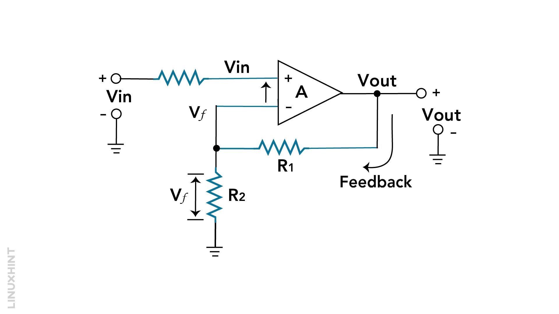
Determine the appropriate values for feedback resistances, R1 and R2. You have to stabilize a non-inverting amplifier circuit using an operational amplifier with an open-loop voltage gain (AVOL) of 220,000. Your targeted closed-loop gain is 40.
Solution:
A general closed-loop feedback equation is:

To get feedback fraction β, rearrange the above equation:
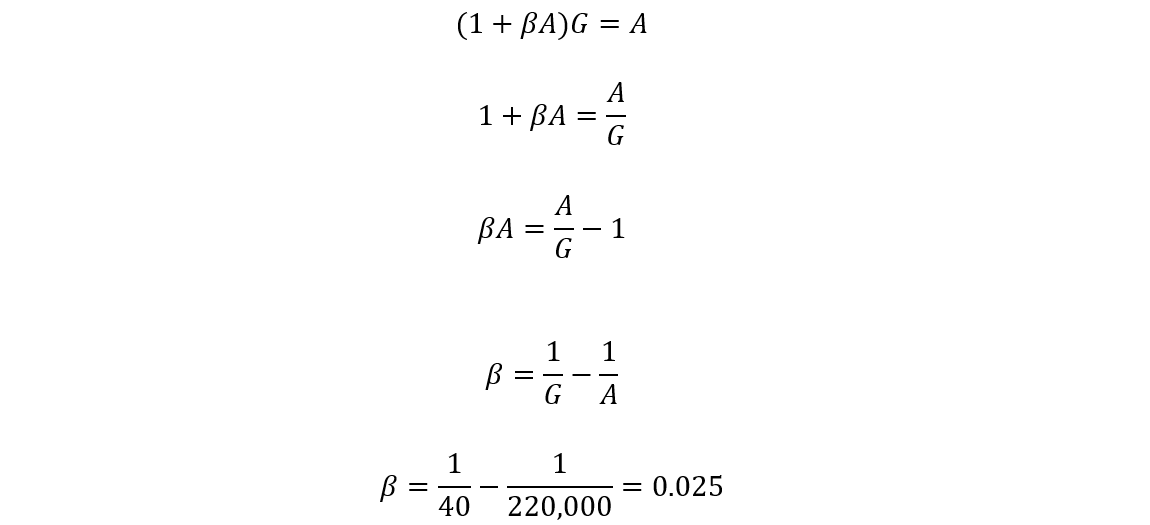
In this case, the open loop gain is too high. So, the feedback fraction β will be approximately equal to the reciprocal of closed-loop gain 1/G. As the value of 1/A is too small, approximately equal to (0.025).
The resistors R1 and R2 in the above configuration form the series-voltage potential divider circuit. You can find the closed-loop voltage gain as follows:

Let’s assume the value for R2 as 1000 Ω (1 kΩ). Then the value for R1 can be written as

So, for the non-inverting amplifier circuit with a gain of 40, you need to select the R1 of 39 kΩ and R2 of 1 kΩ.
Difference Between Positive and Negative Feedback Systems
You can find the difference between the positive and negative feedback systems in below given table:
| Feedback Type Differences | Positive Feedback | Negative Feedback |
|---|---|---|
| Definition | In this feedback, reference feedback and input signals are added. | In this type, the output feedback is subtracted from the reference input. |
| Nomenclature | Positive feedback or Regenerative feedback. | Negative feedback or Degenerative feedback. |
| Purpose | Amplifies or increases a signal. | Stabilizes or regulates a signal. |
| Effect on System | Can lead to unpredictable behavior and oscillations. | Promotes predictability and steady-state operation. |
| Gain Direction | Increases system gain. | Reduces the gain of the system. |
| Usage | Audio amplifiers, and relaxation oscillators. | Operational amplifiers (Op-Amps), feedback control systems. |
| Stability | Often leads to instability. | Improves system stability. |
| For example | Schmitt triggers and flip-flops. | Voltage amplifiers, and temperature controllers. |
Applications and Properties of Negative Feedback System
Negative feedback systems have many applications in general electronics. These systems improved the system instability, the linearity of the system, frequency response, and step response. Due to these benefits of negative feedback systems, many amplifier circuits across electronics possess negative feedback systems.
Some detailed descriptions of negative feedback systems are given below:
Stability: A negative feedback system reduces the deviations from the desired point, resulting in a more stable system. For example, a thermostat makes sure that the temperature remains close to the chosen value.
Accuracy: Negative feedback systems improve the system accuracy by minimizing errors. In an amplifier circuit, the negative feedback reduces the distortion and produces a more stable signal at the output.
Bandwidth Control: You can also control the bandwidth of the amplifier with the help of a negative feedback system. This makes them suitable for several applications. These applications include audio amplification to radio frequency amplification.
Noise Reduction: Negative feedback can decrease unwanted noise and interference. Noise reduction has multiple applications in the field of audio systems and communication devices.
Dynamic Response: Negative feedback systems have dynamic response capability. These systems can adjust accordingly to given conditions. An example of dynamic response includes the car cruise control system.
Effect of Negative Feedback on Bandwidth
Bandwidth explains the operating frequency range for an amplifier with constant gain. A system with a higher bandwidth means the amplifier can handle more frequencies. Negative feedback reduces the amplifier gain by giving the output at the input side. This improves system stability and linearity, but as a result, also reduces the system gain.
The effect of negative feedback on bandwidth depends on the type and amount of feedback applied. Generally, negative feedback increases the bandwidth by reducing the system gain. The gain bandwidth product, which is the measure of the performance of an amplifier, remains constant regardless of feedback.
For example, consider an amplifier circuit without feedback having a gain of 100 and 10 kHz bandwidth. Applying negative feedback to reduce the gain to 10. This will increase the bandwidth to 100 kHz. The gain-bandwidth product is still 100 × 10 kHz = 1 MHz in both cases.
However, the negative feedback also affects the cutoff frequencies of the amplifier. These are the frequencies where the system gains drops from the maximum value. Negative feedback lowers the cutoff frequency and raises the upper cutoff frequency. This will result in widening the frequency response curve of the amplifier. The net effect of negative feedback on bandwidth is to trade gain for bandwidth.
This means that applying negative feedback will increase the range of frequencies that an amplifier can handle. But all this comes at the cost of reducing its amplification factor.
Conclusion
A Negative feedback system can control or adjust the output by serving a part of the output at the input side. This feedback generates an error signal, which will give you a more stable system. This error signal is dynamic and drives the complete system. A negative feedback system can improve system accuracy and also control the bandwidth. This feedback system is used in amplifier circuits such as noise cancellation or car cruise control systems. Read more about the detailed description of negative feedback in this article.