Multivibrators
The digital and electronic circuits use the multivibrator to take different forms of waveform as input to perform different tasks. These multivibrators are used like flip-flops and may be as harmonic generator which is used by sequential circuits for their proper working.
There are three types of multivibrators
1: Bistable Multivibrators
Bistable multivibrator is the second name of flip-flop with both of its states being stable. These states always maintain their presence until two external trigger pulses are applied to fully SET-RESET them. The other name for bistable multivibrators is toggle latch or Bistable latch.
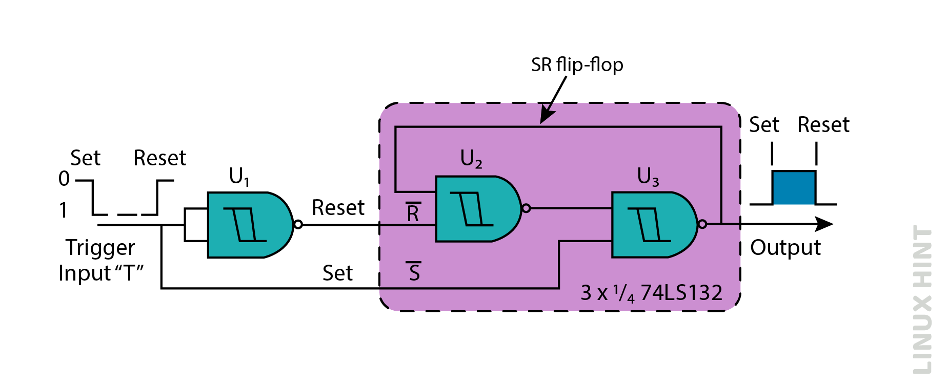
To develop a simple circuit of bistable multivibrators by connecting a pair of Schmitt NAND gates to develop an SR latch. Bistable is developed by two NAND gates, U2 and U3, and U1 is used to trigger this circuit. Both the states are either HIGH or LOW in the bistable multivibrator. There are many uses of this circuit such as counter, frequency divider, and memory element in a computer.
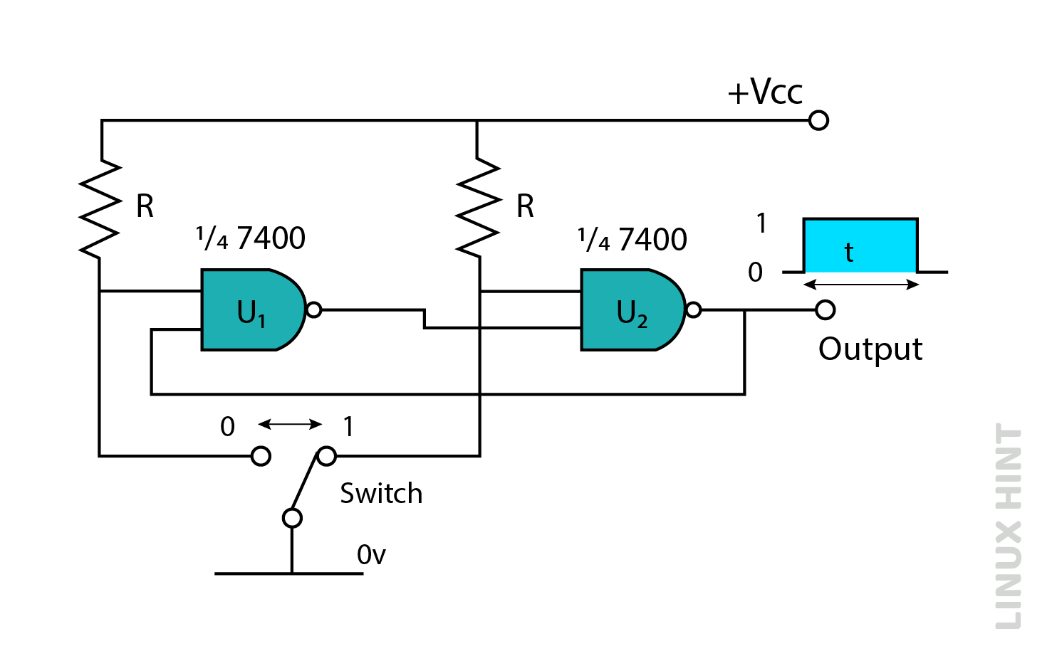
The circuit given below is a representation of a bistable multivibrator, two NAND gates are used to build this circuit. This circuit contains the single pole double throw switch to manually control this bistable multivibrator and give HIGH or LOW output.
2: Monostable Multivibrators
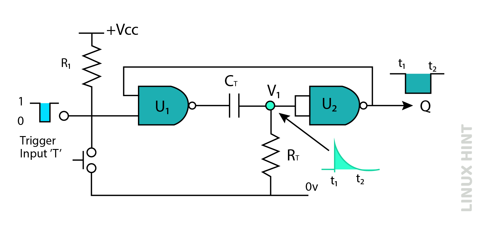
This vibrator is also known as one shot because it is used to increase the short sharp pulse to a much wider pulse, which is used where large timing is required. It produces either a HIGH or LOW pulse when it is triggered by the start signal. This start signal initiates the state of the multivibrator at (t1), which will remain until it reaches (t2), and this state can be found by the timing capacitor CT and resistor RT.
The RC time constant helps the monostable multivibrator remain in one state until its time ends. Idleness or rest is the only state of this monostable multivibrator.
The above circuit is a monostable multivibrator built by two NAND logic gates. The circuit is working according to the state of the clock input and the simple functions of both NAND gates. A negative input trigger produces a LOW output in this case. The time period is determined by the formula, which is given as
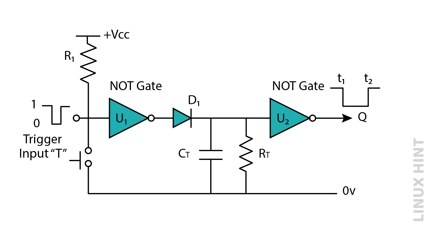
The above circuit is a monostable multivibrator built by two NOT logic gates. The circuit is working according to the state of the clock input and the simple functions of both the NOT gates. The time period for the monostable build by NOT gate is given as
3: Astable Multivibrators
Astable multivibrators are the most commonly used multivibrators, which oscillate between LOW and HIGH states and repeat their state back. This is an ideal component for clock and pulse generation due to its property of continuous switching between LOW to HIGH and HIGH to LOW, and it’s always switching in two logic levels.
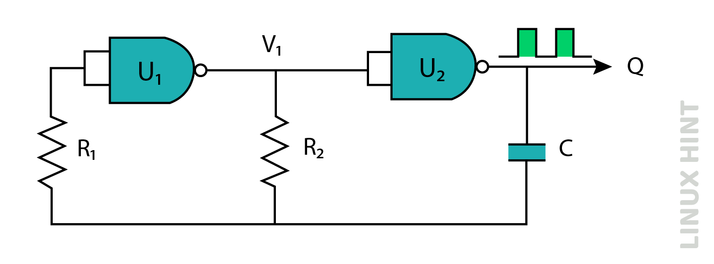
The above image is the prototype of an astable multivibrator. Two 74HC04 hex inverter ICs are used in the construction of astable multivibrators. The time constant for astable multivibrators is given by the formula is
The frequency is given by the formula:
Consider an example of an astable multivibrator R2 = 10 k Ohms and the value of capacitor C = 45 nf. Find the frequency:
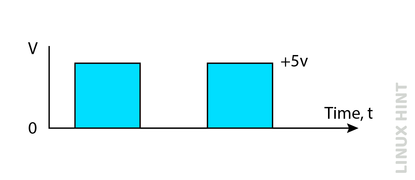
The graphical view of this is given as:
NE555 Astable multivibrator
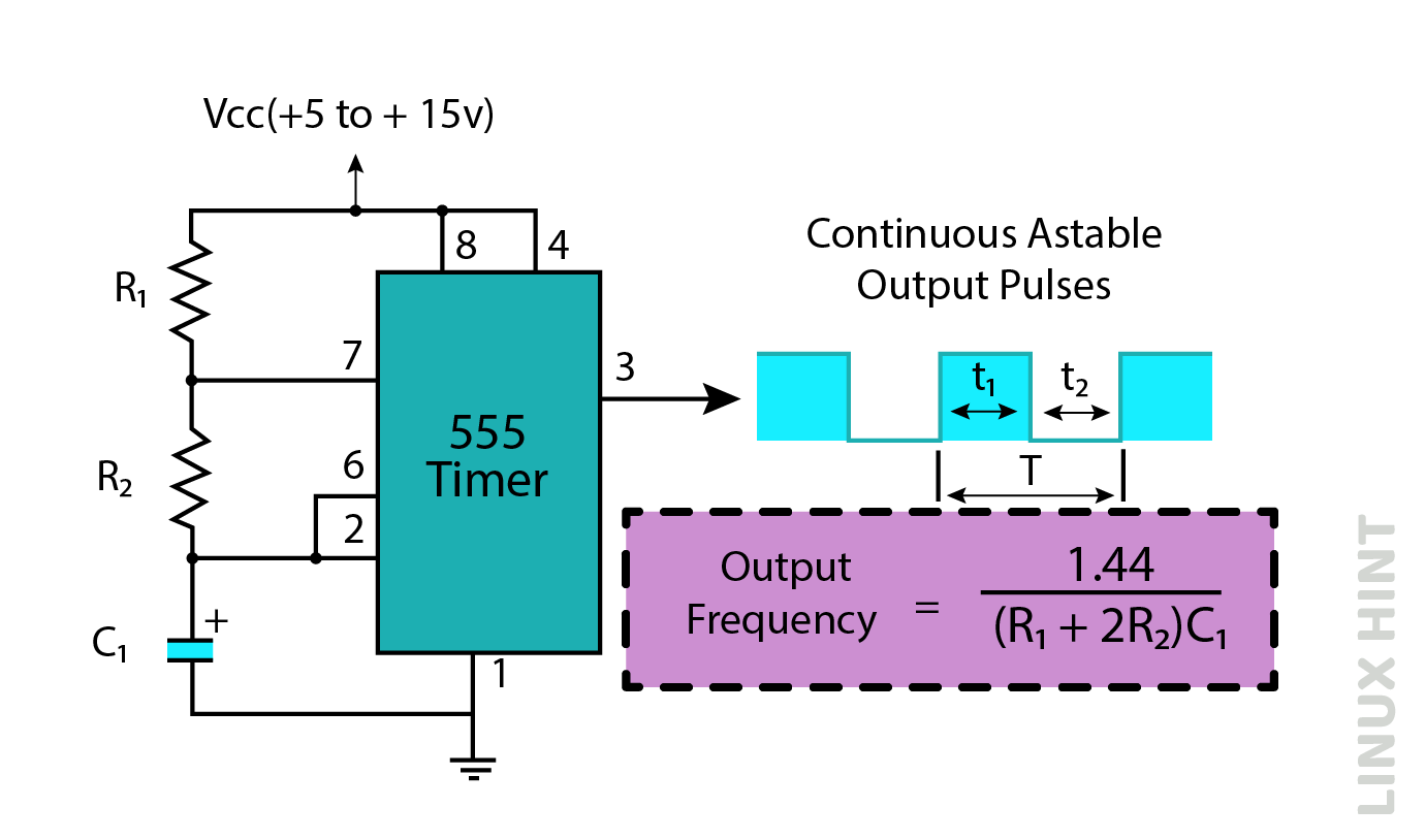
The above give circuit is also an Astable multivibrator, and it continuously gives the output. The stable oscillation function is performed by connecting commonly to both the 2 and 6 pins, which are used to retrigger itself on each cycle. The capacitor uses both R1 and R2 to charge itself, but the discharge occurs only with R2. The time period formula for both t1 and t2 is given as
Conclusion
Multivibrators are the main components present in the electronic devices used to produce different types of waveforms such as square waves, sawtooth, and many more. There are different types of multivibrators based on their function and structure, such as monostable, astable, and bistable.

