Both the AC/DC and DC/DC power converters and power supplies use the transformer. Transformers are a vital component of any electrical circuit. It can step up and step-down voltages to a safe limit. Transformers are a must-have component for any circuit that has DC output and line voltage input. In the DC/DC circuit, the transformer works by switching the PWM signals instead of the AC sinusoidal signal.
Multi-winding transformers can give us the output power with high efficiency and over multiple rails. These transformers have multiple secondary coils to increase or decrease the input voltage to the desired value. These transformers are also used for the isolation of multiple rails in a power system.
Quick Outline:
- What is Multiple Winding Transformer
- Introduction to Dual Voltage Transformers
- Multiple Winding Transformer Taps
- Voltage Configurations for Multiple Winding Transformers
- What is Center Tapped Multi Winding Transformer
- Center-Tapped Transformers Using Dual Voltage Transformer
- Conclusion
What is Multiple Winding Transformer
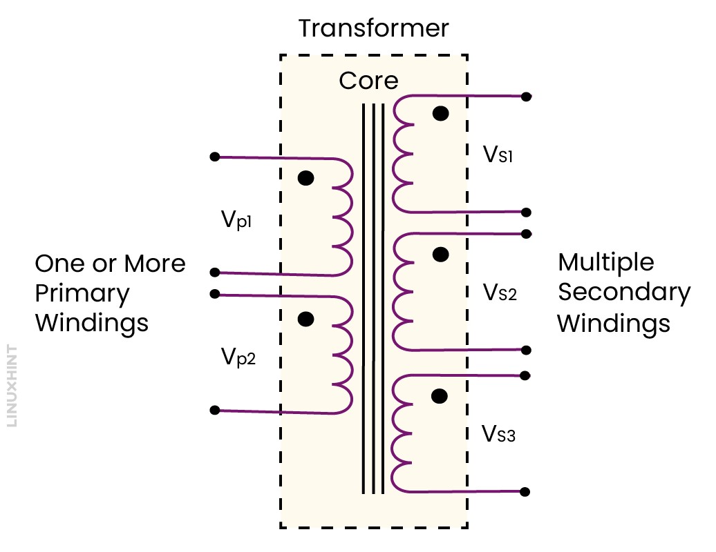
Transformers that have more than one winding on either side, are called Multiple Winding Transformers. They usually have one primary winding and two or more secondary windings. These transformers are useful for different purposes, such as voltage regulation, isolation, and impedance matching.
Multiple-winding transformers work the same way as ordinary transformers. One difference is that they have more than one winding on either side. To connect them together, we need to check the voltage polarities of each winding, which are marked by dots. The dots show the positive (or negative) end of the winding.
Transformers work on mutual induction, which means the voltage in each winding is proportional to the number of turns, such as shown below:
The power in each winding is the same, so the ratio of turns is equal to the ratio of voltages. For example, if the primary winding has 10 turns and 100 volts, and the secondary winding has 5 turns, then the secondary voltage is 50 volts. This is how multiple-winding transformers can have different output voltages for different coils.
A transformer that can have different secondaries with variable wire turns. The number of turns affects the voltage of the electricity. More turns mean higher voltage and fewer turns mean lower voltage. So, a transformer can make different voltages for different devices from one source of electricity. This is useful for electronic circuits, such as power supplies and converters.
Following is a multiple-winding transformer with multiple secondary winding connections. Each of these secondary windings provides a different voltage output.
We can use the primary winding individually or connect it with a pair of different other windings to operate a transformer. However, the secondary winding connection depends on how much voltage we need on the output side. Secondary winding in parallel configuration is only possible if the two windings which are connected must be electrically identical. In other words, their current and voltage ratings must match.
Introduction to Dual Voltage Transformers
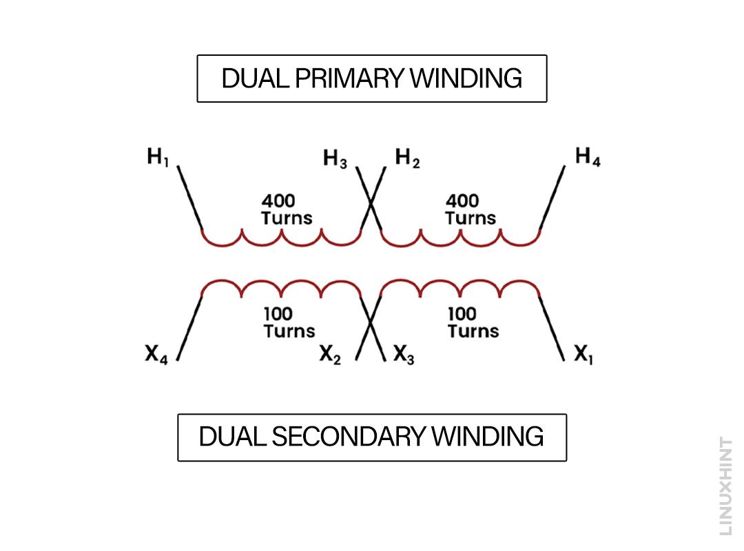
Dual Voltage Transformers contain dual primary windings and dual secondary windings. The voltage and current specifications of both primary are identical. Similarly, the voltage and current ratings of both secondary windings are also the same. These transformers are designed in such a way that they can be used in different applications. We can change the transformer taps of these windings to create a series and parallel combination for higher current and voltage requirements. These types of multiple-winding transformers are referred to as Dual Voltage Transformers.
Multiple Winding Transformer Taps
Some transformers are designed in such a way that you can modify their turn ratio by changing the primary and secondary side connections. These connections on the primary or secondary sides of a transformer are called transformer taps.
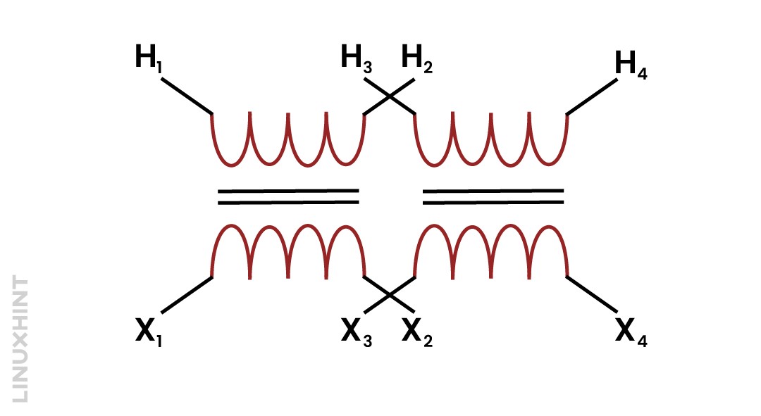
The transformer connection diagram shows the single-tap connection of primary and secondary windings. In this image, we can see the turns of the secondary (400) are more than the turns of the primary (100) coil. So this is the connection diagram of a step-down transformer having a dual primary and dual secondary winding.
The given transformer has dual primary and dual secondary windings. In these windings, each end is called a terminal and there is a pair of terminals for each winding.
Primary or high-voltage side terminals are named H₁ and H₂.
While looking at the transformer from the secondary side, the high voltage terminal of the transformer is labeled as H₁. According to the CSA, this has been made an industry standard for labeling the high voltage terminal when seeing it from the secondary side.
Similarly, the other high-voltage winding side terminals are labeled as H₃ and H₄.
From the figure we can see that for labeling the secondary terminal of a high-voltage transformer the letter used is X. The two secondary or low-voltage side terminals are labeled X1, X2, and X3, X4.
Transformers having dual winding in each of its primary and secondary winding has the advantage. In this way, each pair of transformer winding is joined either in series or in parallel.
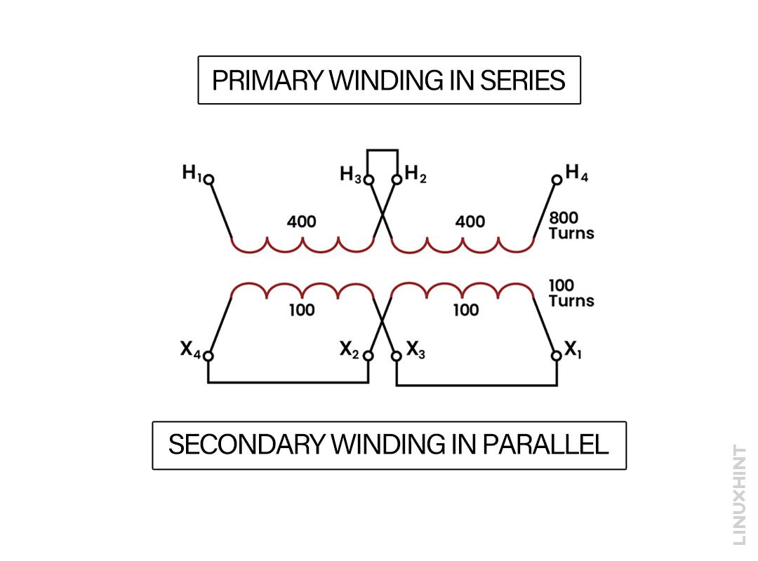
Now consider the transformer tap connection diagram below. This configuration also contains dual primary and dual secondary winding. Here, both windings on the primary side are in series, while the secondaries are in parallel.
From the tap connection, you can see that on the high-voltage side, terminal H₂ is connected with the terminal H₃. So in this way, both the high voltage windings are in series with each other. The number of turns for both of the high voltage primary windings is 400 turns each. So the primary or high voltage side has a total of 800 turns.
Terminal X1 on the low voltage side is linked to terminal X3, while terminal X2 is joined with terminal X4.
The two low-voltage windings, each with 100 turns, are connected in parallel. This creates a single secondary winding which has a total of 100 turns.
So this transformer has an 800-turn primary and a 100-turn secondary and is now configured as a step-down transformer with a turn ratio of 8:1.
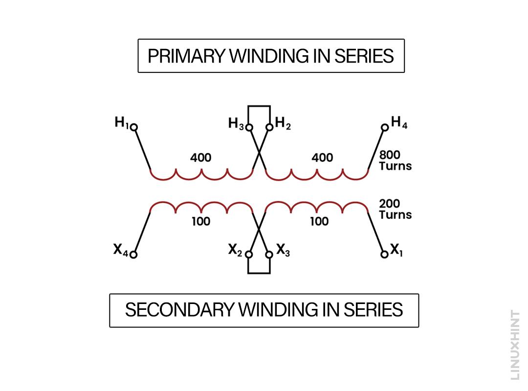
Now consider the same transformer having a different configuration of tap connections. In this scenario, the high-voltage windings and low-voltage windings are interconnected in series.
The high-voltage windings have two 400-turn primary windings, which are joined in series. This will create a high-voltage single winding with a total of 800 turns. Similarly, the two 100-turn low-voltage windings are also linked in series. This will result in a single secondary winding with 200 turns. So the new modified turn ratio that we will get is now 800:200 or 4:1.
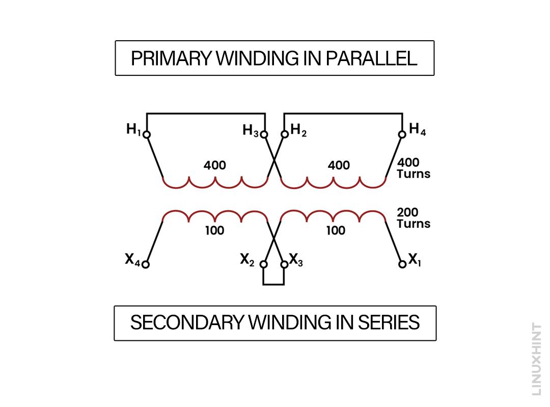
In this configuration of the transformer, both windings of the primary side are in parallel connection, while the connections of both secondary sides are in series. As the primary windings are in parallel, both of the 400-turn primary windings will act as a single primary winding having 400 turns.
Both windings on the secondary sides are connected in series, with each having 1000 turns. Both of these add up to create a single 200-turn secondary low-voltage winding. The new turn ratio that we will get for this transformer configuration is 400:200 or 2:1.
So we have covered different configurations of the transformer with dual primary and dual secondary winding. In this way, we can adjust the primary and secondary tap connections to yield different turn ratios.
Voltage Configurations for Multiple Winding Transformers
Different configurations make it possible to connect the multiple winding transformers. The connection of each type depends on multiple factors like how much is the output voltage we require, and the power bus to which we need to connect a transformer. It also depends on coil configuration whether the primary or secondary sides are connected in series or in parallel configuration.
Let’s take a look at some main configurations of multi-winding transformers:
1. Multi-Winding Transformer Configuration
A multi-winding transformer has dual primary and dual secondary windings. Consider the following multiple-winding transformer given in the image:
Some main characteristics of a multiple-winding transformer are:
- Transformers can have multiple primary windings, multiple secondary windings, or both.
- The maximum voltage on each winding of the high-voltage side is the lower of the two voltages.
- The maximum voltage on each low-voltage winding is the lowest of the two secondary voltages.
- Insulation may be damaged by any voltage higher than the specified ratings.
- Each winding of a transformer can safely handle half the kilovolt-amperes (kVA) rating of the transformer.
- To get the required voltage, we can connect batteries in series or parallel.
2. Multi-Coil Distribution Transformer
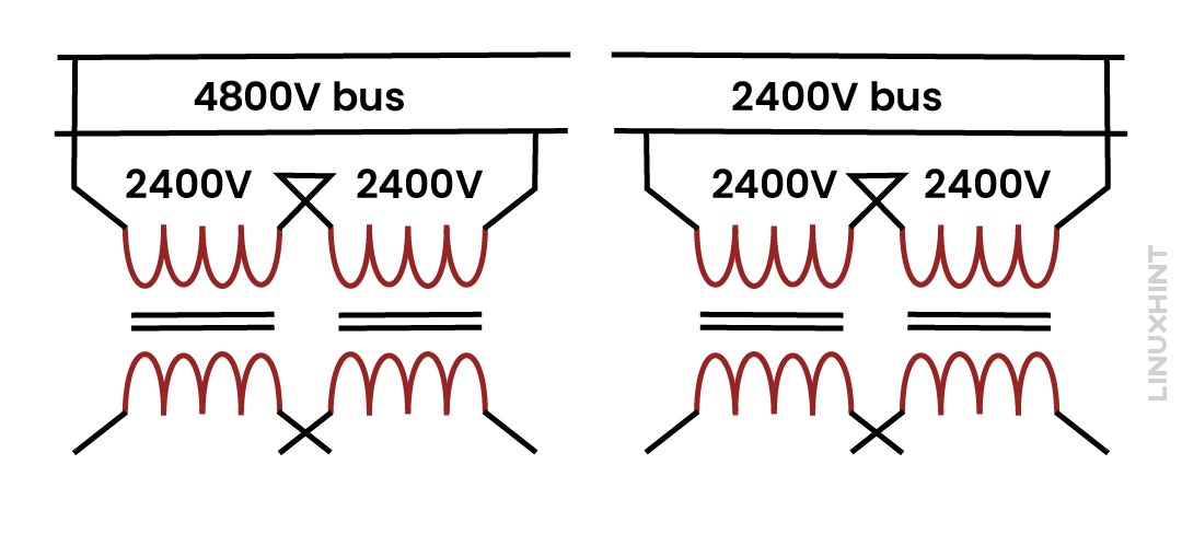
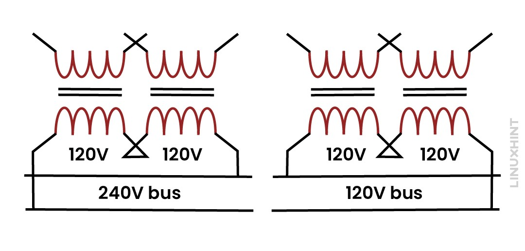
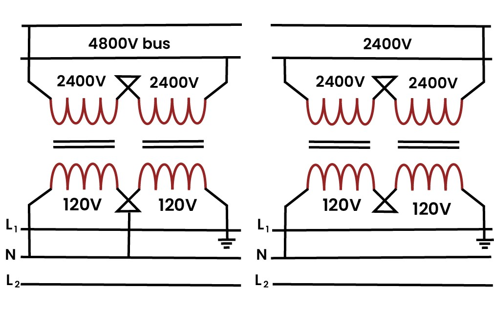
The given transformer is rated as 50 kVA, 2400/4800 V – 120/240 V. From this we can conclude that the high-voltage side can handle a maximum of 2400 V per winding. And this voltage will always be less of the two voltages. Similarly, the low-voltage side or secondary side winding is rated at a maximum voltage of 120 V per winding. Remember, exceeding these voltage ratings can damage the insulation.
Primary Side (High-Voltage) Connection
- If you want to link the high-voltage side of this 50 kVA transformer to a 4800 V bus, you’ll need to connect the two windings in series. In this way, the 4800 V bus voltage will be evenly split, with each winding having to bear the load of 2400 V.
- When connecting the high-voltage side to a 2400 V bus, go for a parallel connection. This will make sure that each of the winding experiences, 2400 V.
Secondary Side (Low-Voltage)Connection
- To connect up the low-voltage or secondary side to a 240 V bus, connect the two windings in series. This divides the bus voltage equally, providing 120 V to each winding.
- If you need to link the low-voltage side to a 120 V bus, use a parallel connection. This way, each winding gets to work with 120 V.
3. Current Calculations
In a transformer, the volt-amperes (VA) rating can be calculated by taking the product of voltage with the current. The transformer which is given in the previous configuration can handle only half of the total kVA. Each high-voltage winding and each low-voltage winding are rated at 25 kVA.
Calculating Current for High-Voltage Winding (Primary):
So, from the above result, we can conclude that the Maximum current the high-voltage winding can handle is 10.4 Amps.
Calculating Current for Low-Voltage Winding (Secondary):
For low-voltage winding, the maximum current it can handle is 208.3 Amps.
Now, let’s look at the combined values when both coils are considered together:
Calculating Current for High-Voltage Winding (Primary) with Full VA:
The maximum current for the high-voltage winding when both coils of the primary are considered is 10.4 Amps.
Calculating Current for Low-Voltage Winding (Secondary) with Full VA:
Again, the maximum current for the low-voltage winding is 208.3 Amps.
So whether we consider a single coil and half the VA or both coils with the full VA, the calculated maximum currents for both the high-voltage and low-voltage windings remain the same. This is due to the specific design and rating of the transformer.
4. Three Wire Connections of Multi-Winding Transformer
Center-tapping the transformer with the single line will result in 120 V output, while double tapping with both lines will give you 240 V.
In three-wire secondary connections (120/240 V), the transformer will deliver the full kVA only when it has a perfectly balanced load. An unbalanced load results in one winding being overloaded. This will result in surpassing the current rating, as each winding can only handle half of the rated kVA.
What is Center Tapped Multi Winding Transformer
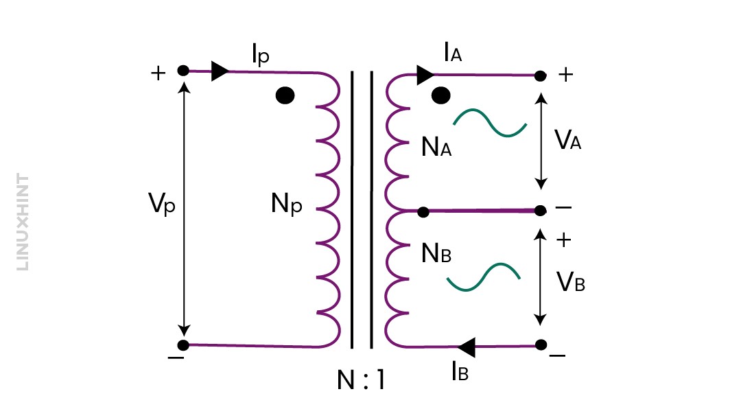
A center-tap transformer is designed to give you two different secondary voltages. These voltages are VA and VB, with a shared connection between them. This setup of the transformer will create a two-phase, 3-wire power source.
The secondary voltages and the supply voltage Vp are equal and in direct proportion. As a result, the power in each winding is the same. The voltages across these secondary windings depend on the turn ratio.
In the diagram above, you can see a standard center-tap transformer. The center tapping point is at the center of the secondary winding. It will create a common connection for two secondary voltages that are equal in magnitude but opposite in polarity. When you ground the center tap, the VA voltage will become positive with respect to the ground. While the VB will become negative and is in the opposite direction. This means they are electrically 180° out of phase.
However, there’s a drawback to using an ungrounded center-tap transformer. Because of the uneven current flow through the third connection, it will result in unbalanced voltages in the two secondary windings. You will see this case especially when loads are unbalanced.
Center-Tapped Transformers Using Dual Voltage Transformer
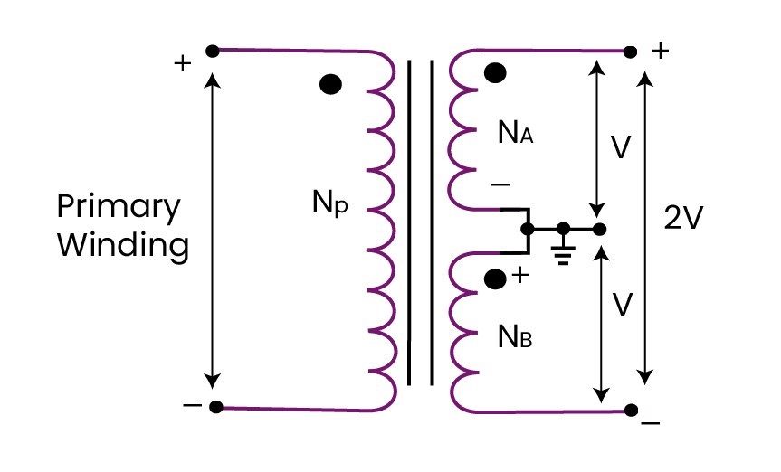
We can also create a center-tap transformer by using the dual voltage transformer. To do this, connect the secondary windings in series and their center link serving as the tap. If the output of each secondary winding is V, then the total output voltage of the secondary will be 2V.
Conclusion
Multiple winding transformers have many applications in electrical and electronic circuits. These dual-winding or multiple-winding transformers can supply different output voltages depending upon the number of secondary turns ratio. Multiple winding transformers can be interconnected in series or parallel configurations to output the increased voltages or currents. You can also create a center-tapped transformer by linking both of their secondary windings in series.


