Thyristors are also called silicon-controlled rectifiers. They are multi-layer semiconductor devices. Due to this reason, they include silicon in their terminology. The “controlled” part of the term indicates the requirement of the gate signal to turn them ON and once they are turned on, they act like rectifiers. Thyristors and transistors are similar in construction. This article describes thyristors in detail.
Thyristors
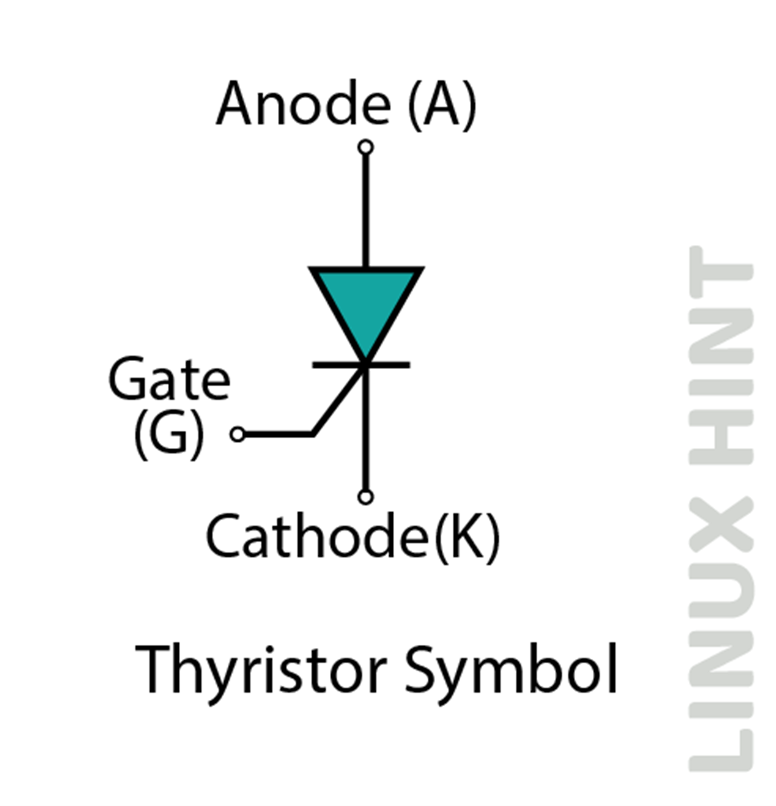
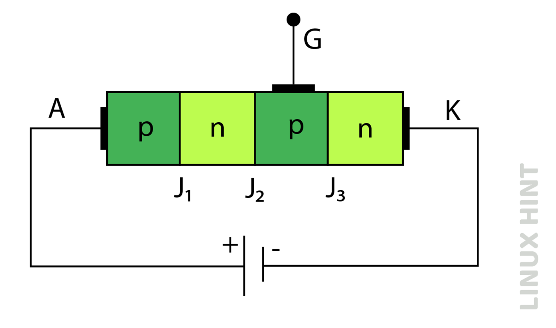
A thyristor is a four-layer semiconductor device with three numbers of PN junctions in series. These terminals are called Anode, Gate, and Cathode. Three PN junctions in its construction can be switched ON and OFF at a given speed and for a variable length of time. The symbol of the thyristor is shown below:
A thyristor, like a diode, conducts current in one direction, and depending on how its gate is operated, it can be an open switch or a rectifying diode. SCR-controlled silicon devices, along with Triacs, Diacs, and UJTs, can handle large AC voltages and currents like very solid-state AC switches.
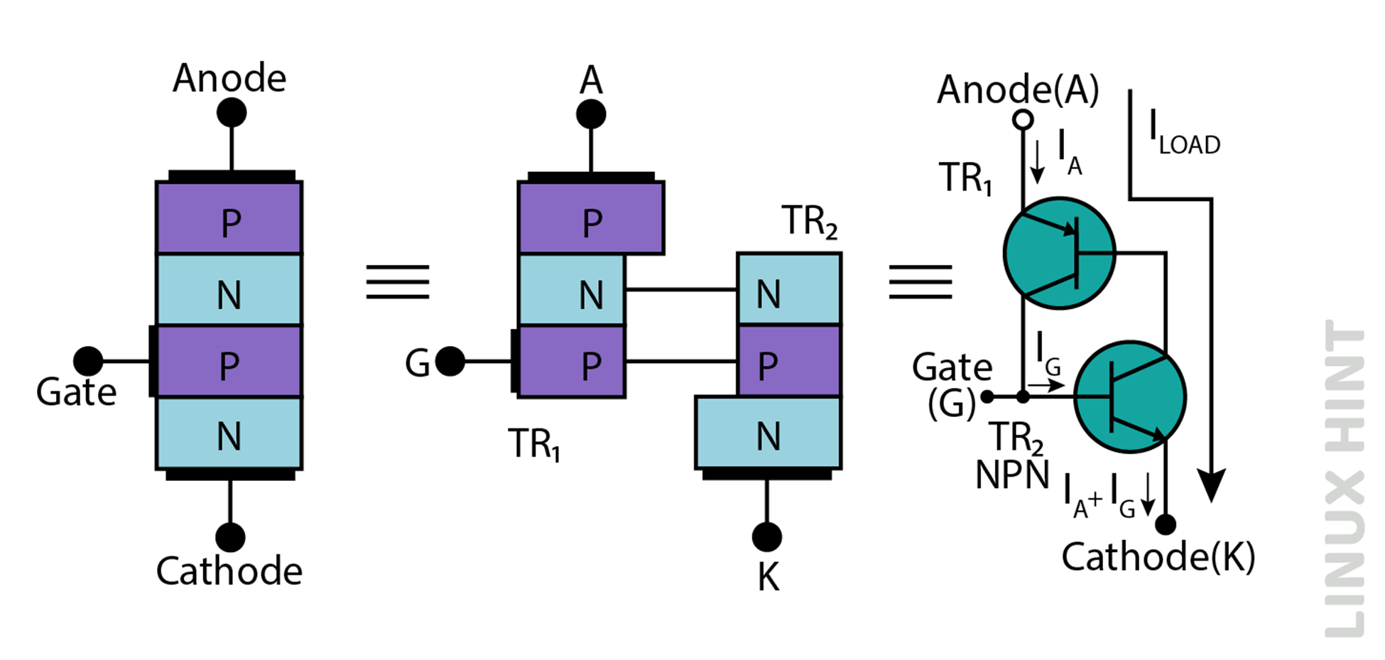
Construction – Two Transistors Based Structure
The collector current of the first NPN-based transistor TR2 supplies directly to the base of the second PNP transistor TR1, while TR1 supplies into TR2. Each transistor receives a base-emitter current from the other collector-emitter, so they are connected.
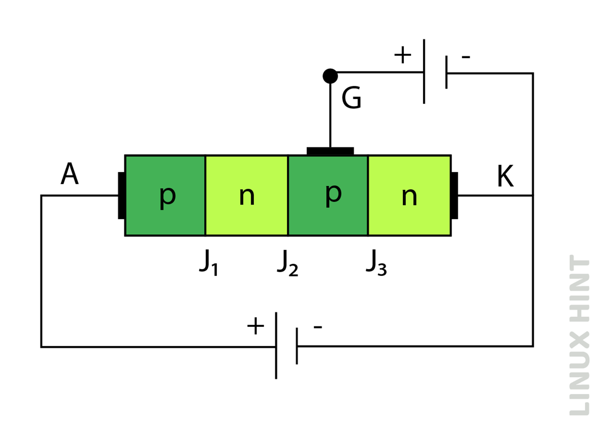
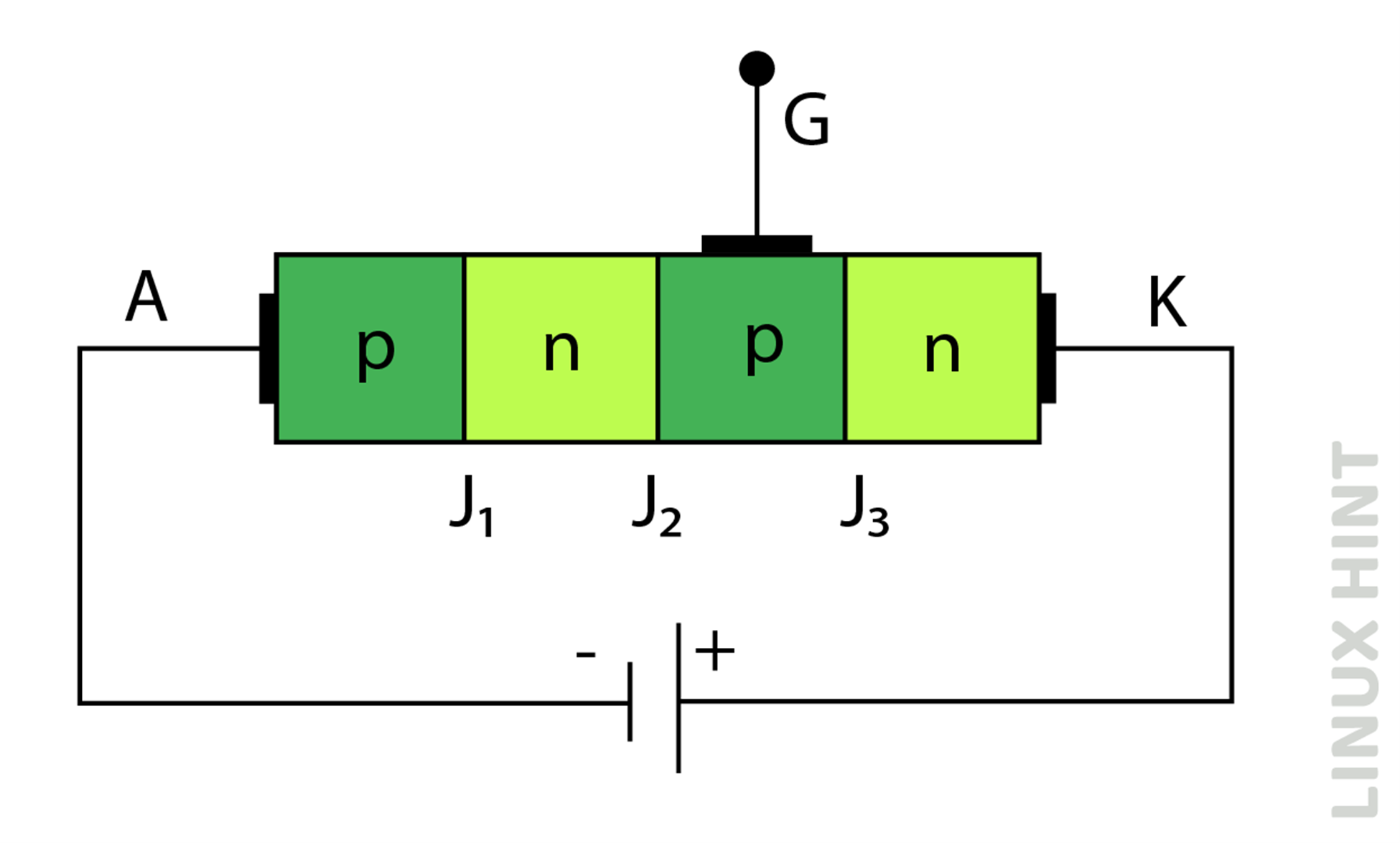
When the thyristor’s anode terminal is negative, the central N-P junction is forward biased, while the two outer PN junctions are reversed biased, making it behave like a diode. Therefore, the thyristor stops the current until the voltage drop of the second output junction exceeds the high voltage level, allowing it to conduct without any gate signal. This is a disadvantage of thyristors because overvoltage recovery, overtemperature, and spikes can put thyristors into conduction mode.
When the anode terminal is more positive than the cathode, the outer P-N junction is forward-biased while the center terminal is reverse-biased. Therefore, no current flows. When positive, current is injected into the base of NPN transistor TR2 and causes the current accumulation of the transistor TR1. This leads the TR1 collector current to increase the TR2 base current, and so on.
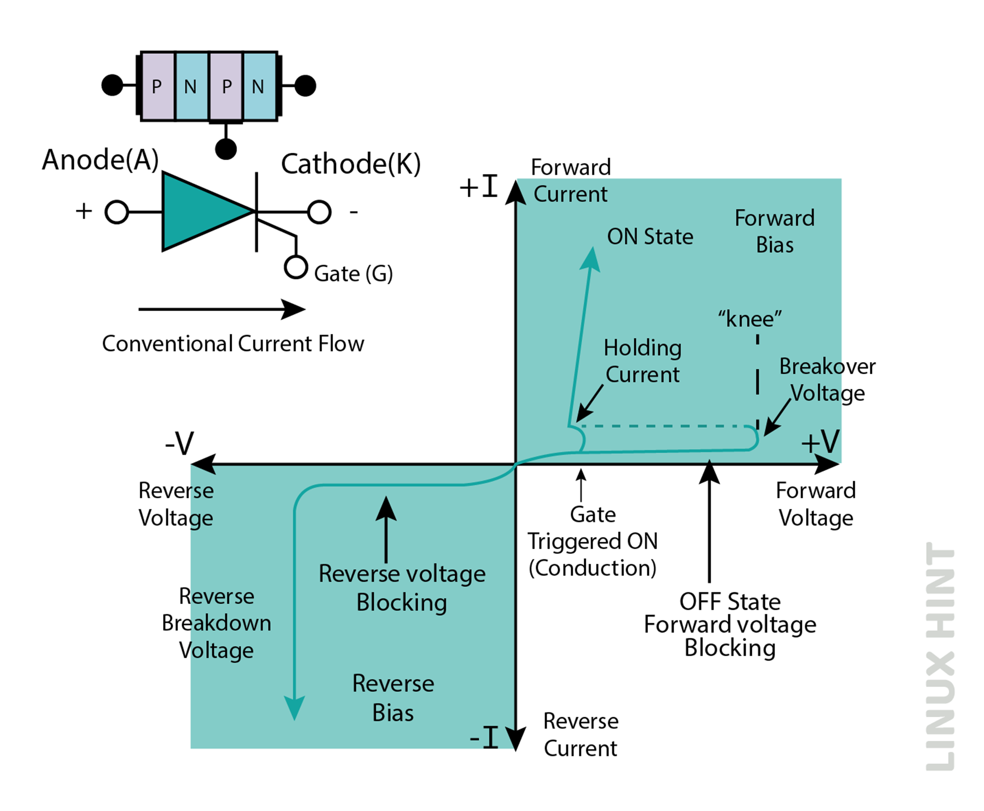
I-V Characteristics
When the thyristor is turned “ON” and starts to conduct current, the gate signal goes out of control due to the latching phenomenon occurring between two internal transistors. As soon as the thyristor conducts and is fully ON, the gate signal or pulses shall have no effect.
As the control is internally regulated, the amplitude and length of the gate pulse do not affect device performance. An instant gate pulse to put the device in conduction mode is enough to keep the device in an “ON” state even if the gate signal is removed after.
Therefore, the thyristor is a bistable latch with two stable states: “OFF” and “ON”. A rectifier stops the current on both sides of the AC waveform without the gate signal, and once it’s triggered, it will not “turn off” again using its gate pulse.
Once the thyristor attains an “ON” state and the current has passed, it can be turned “OFF” again either by removing the supply voltage removing the Anode current (IA), or reducing the Anode-cathode current.
Since the thyristor can be turned “off” by reducing the anode current below its minimum value, the SCR will automatically turn “off” at some values close to the crossing point of half cycles. It stays “off ” until the next gate’s trigger pulse.
The sinusoidal AC voltage switches polarity over every half cycle, the thyristor turns “off” at 180 degrees of positive waveform. It is known as a natural commutation phenomenon in thyristors.
Thyristor Operational Modes
Thyristors can operate in three of its working modes. The characteristics of these operation modes are discussed below:
Forward Conduction Mode
Forward conduction mode is the standard operational mode of thyristor. When thyristors are switched on through an external trigger pulse, they remain in forward conduction mode until the current decreases below the holding current level. For switching thyristors into forward conduction mode, below biasing arrangements are required:
Forward Blocking Mode
In forward blocking mode, the thyristor blocks any current flow even if the external forward voltage is applied for switching on the thyristors. The thyristors continue blocking its operation. For switching thyristors into forward blocking mode, the below biasing arrangement is required:
Reverse Blocking Mode
In reverse blocking mode, current attempts to flow in the reverse direction as compared with its normal thyristor operation. The thyristor blocks these reverse currents and remains in the off state. For switching thyristors into reverse blocking mode, the below biasing arrangement is required:
Application – Phase Control
The SCR is “off” at the beginning of the positive half-cycle. The SCR is driven by the input of the gate and remains locked completely “ON” by the positive cycle. Triggering the thyristor at the beginning of the half cycle (θ = 0) will keep the load (light) “ON” during the positive half of the input AC waveform at 0.318 x Vp.
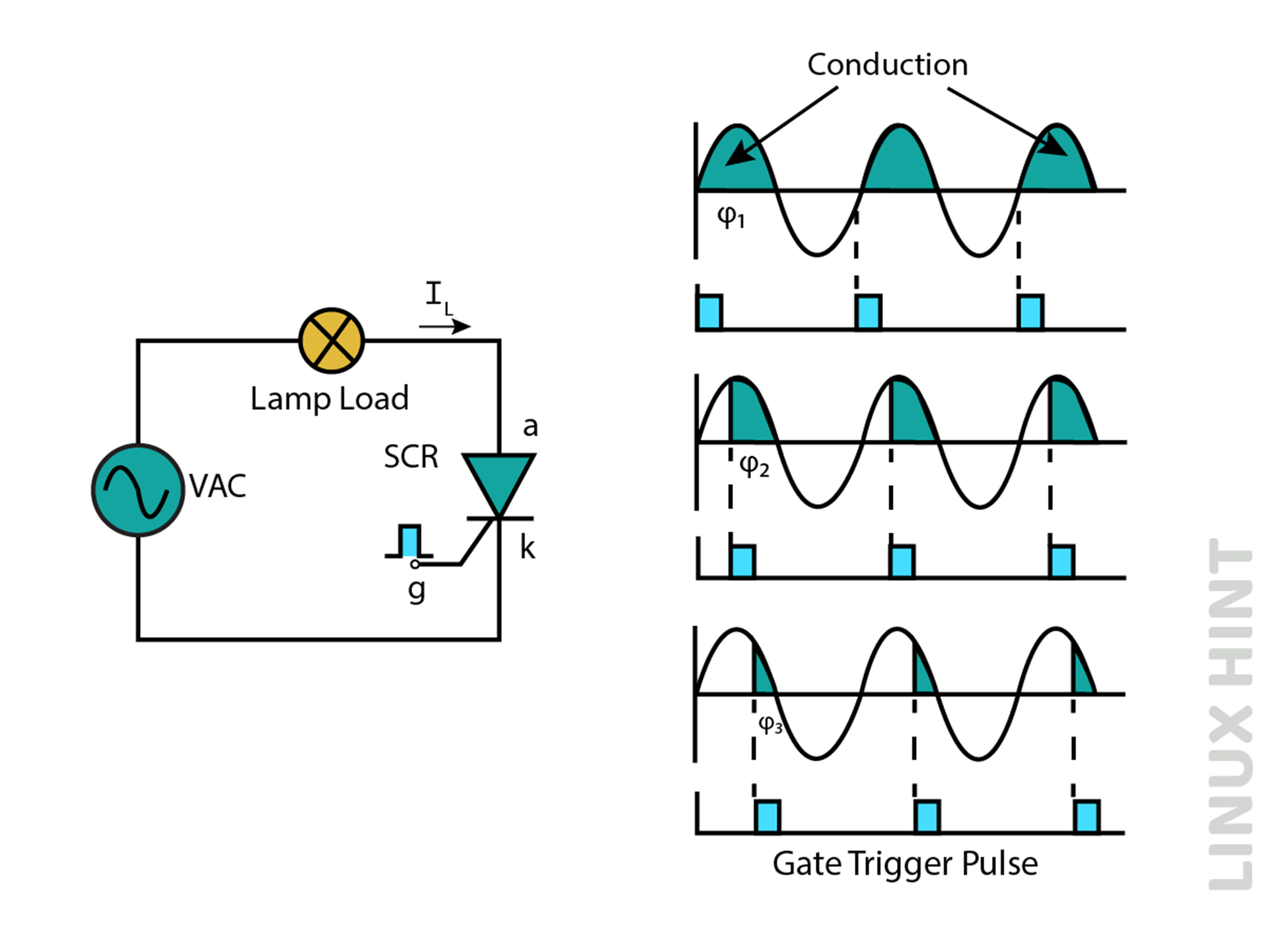
As the gate pulse increases over a full half cycle from ‘0’ degrees to 90 degrees, the lamp will shine for a short time and receive a low average voltage, reducing the brightness.
Conclusion
Thyristors can conduct current to high electrical loads. They can be turned on by a short gate triggering pulse and then the gate pulse can be removed. Thyristors do not require constant gate-triggering pulses for their operation.