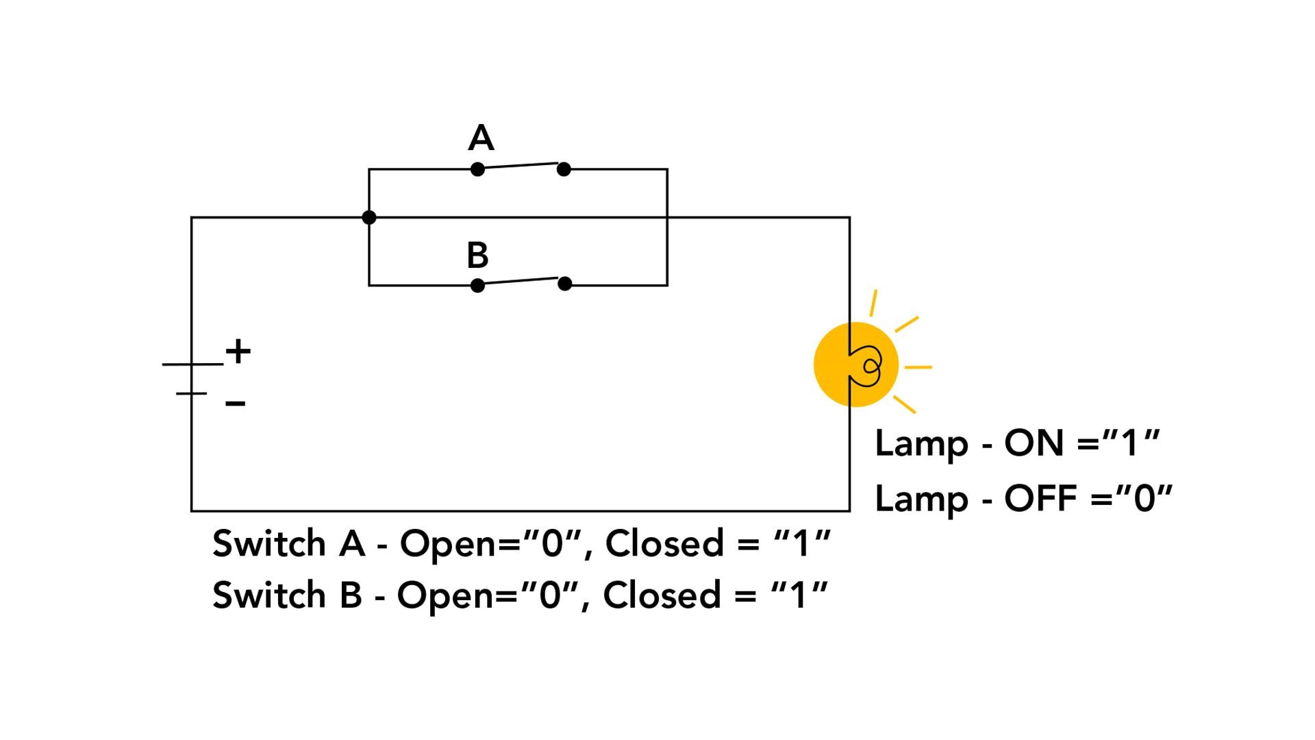
OR Gate
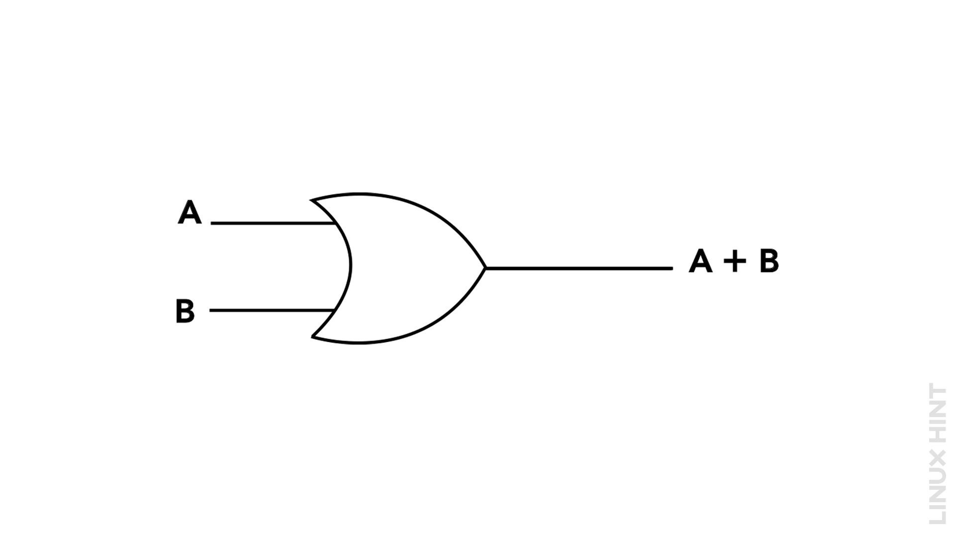
The OR gate takes multiple input signals and produces an output signal based on their logical OR operation. It follows the principle that if any of the input signals is HIGH (1), the output signal will also be HIGH (1). Only when all input signals are LOW (0) will the output signal be LOW (0). The behavior of an OR gate can be summarized as follows:
| A | B | A OR B |
|---|---|---|
| 0 | 0 | 1 |
| 0 | 1 | 1 |
| 1 | 0 | 1 |
| 1 | 1 | 1 |
The equation representing the operation of an OR gate can be expressed using Boolean algebra. For a two-input OR gate, the equation is:
Here, A and B represent the input signals, and the “+” symbol denotes the logical OR operation.
Example: Two-Input OR Gate
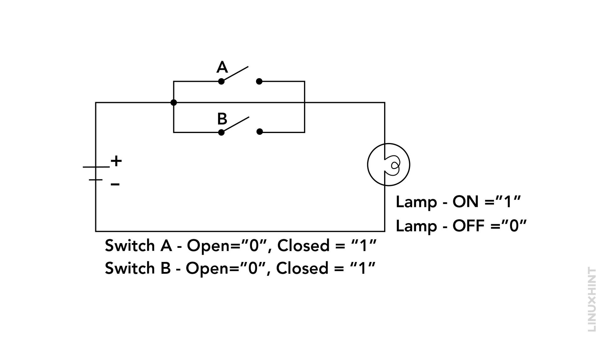
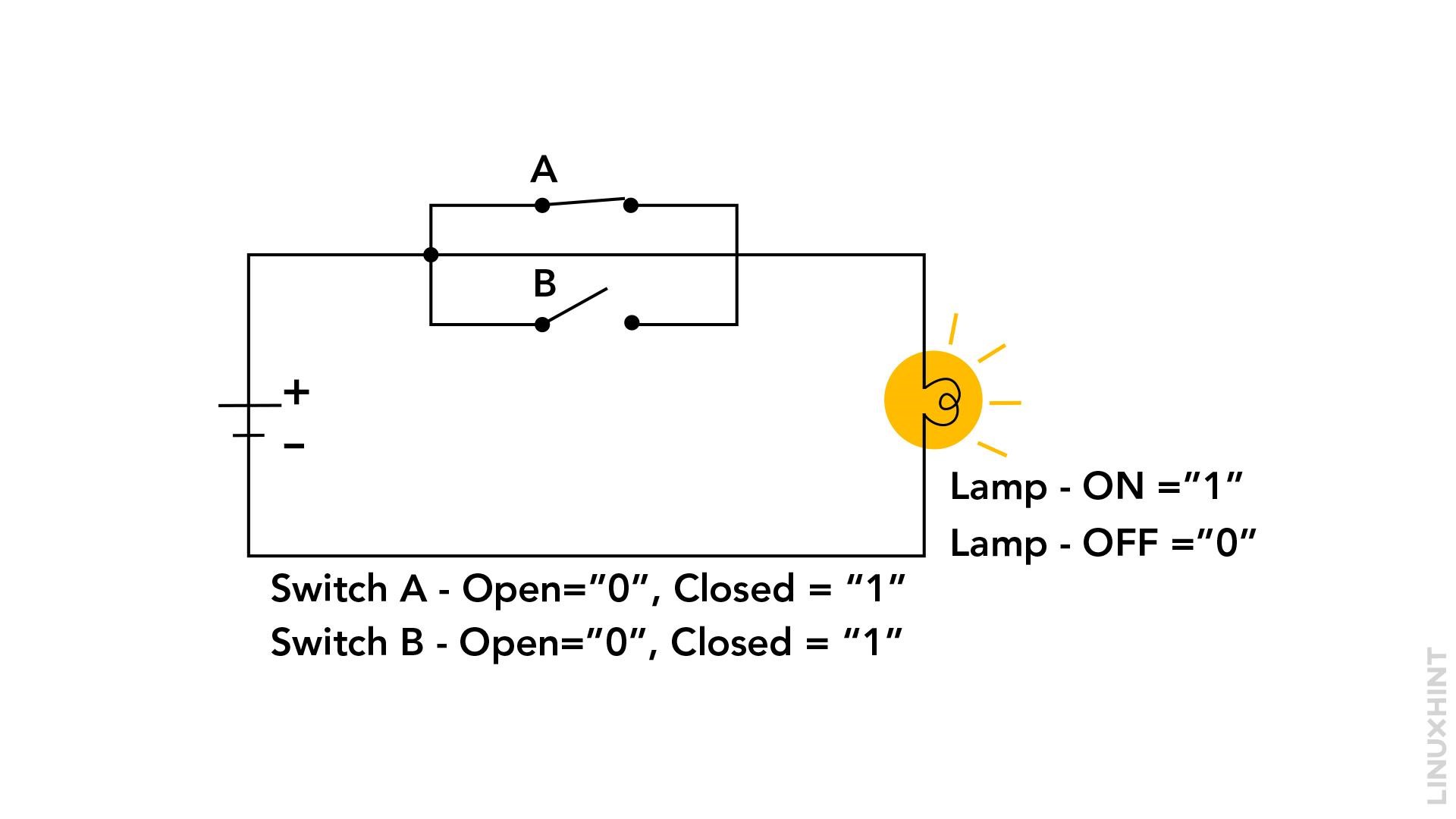
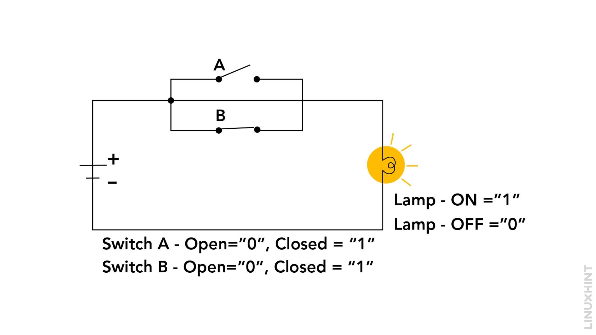
Here is an example of a two-input OR gate with input signals A and B and, we want to determine the output signal based on the given inputs.
When both the inputs are Low for the OR gate then:
When switch A is closed and switch B is open as one input for the gate is high and the other is low then:
When switch A is open and switch B is close as one input for the gate is low and the other is high then:
When switch A is closed and switch B is also closed as both the inputs for the gate are high then:
Conclusion
The logic OR gate is a fundamental component in digital circuits, serving the purpose of combining or evaluating input signals. Understanding its function, equation, and practical applications is essential for anyone involved in electronics or digital logic. In this tutorial, we explored the function and equation of an OR gate and provided examples to illustrate its operation.


