AND Gate
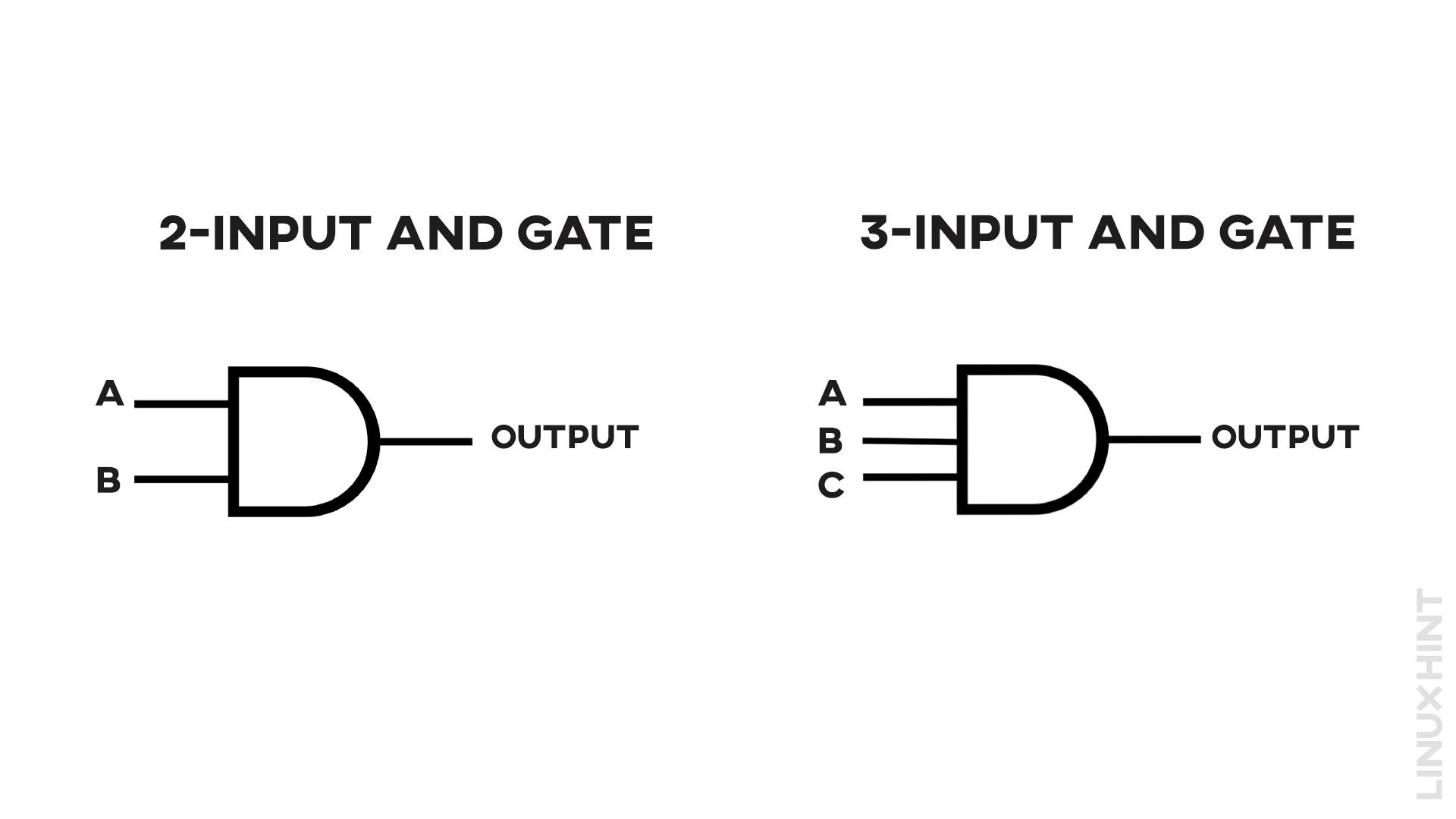
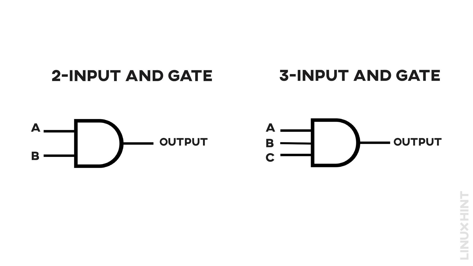
The AND gate follows the multiplication logic of all of its inputs. It means that every input plays its role to generate the output in the AND gate. If any of the input is low or false, output from the AND gate turns false. It is represented as below:
2-Input AND Gate Boolean Expression
The Boolean expression for AND gate is represented as:
The multiplication of two inputs A & B provides the output O.
This boolean expression describes that: “If both A and B are true, then O is true”.
2-Input AND Gate Truth Table
An AND gate requires all the inputs to be high for returning a high output. A truth table showing all possible combinations of input with output is tabulated below:
| Input A | Input B | Output |
|---|---|---|
| 0 | 0 | 0 |
| 0 | 1 | 0 |
| 1 | 0 | 0 |
| 1 | 1 | 1 |
3-Input AND Gate Boolean Expression
The Boolean expression for AND gate is represented as:
The multiplication of two inputs A & B provides the output O.
This boolean expression describes that: “If all A, B & C are true, then O is true”.
3-Input AND Gate Truth Table
An AND gate requires all the inputs to be high for returning a high output. A truth table showing all possible combinations of input with output is tabulated below:
| Input A | Input B | Input C | Output |
|---|---|---|---|
| 0 | 0 | 0 | 0 |
| 0 | 0 | 1 | 0 |
| 0 | 1 | 0 | 0 |
| 0 | 1 | 1 | 0 |
| 1 | 0 | 0 | 0 |
| 1 | 0 | 1 | 1 |
| 1 | 1 | 0 | 0 |
| 1 | 1 | 1 | 1 |
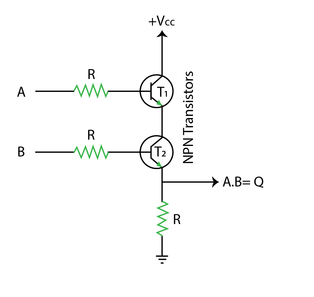
2-Input Transistors Based AND Gate Circuit
AND gate can be constructed with NPN transistors and two resistances as shown in the figure. This is also known as the Resistor-Transistor Logic of the AND Gate.
The two transistors T1 & T2 should both be closed to make a completely closed path for the signal from Vcc to R. If any of the transistors is open, the path breaks and the output returns zero.
AND Logic Gate Operation
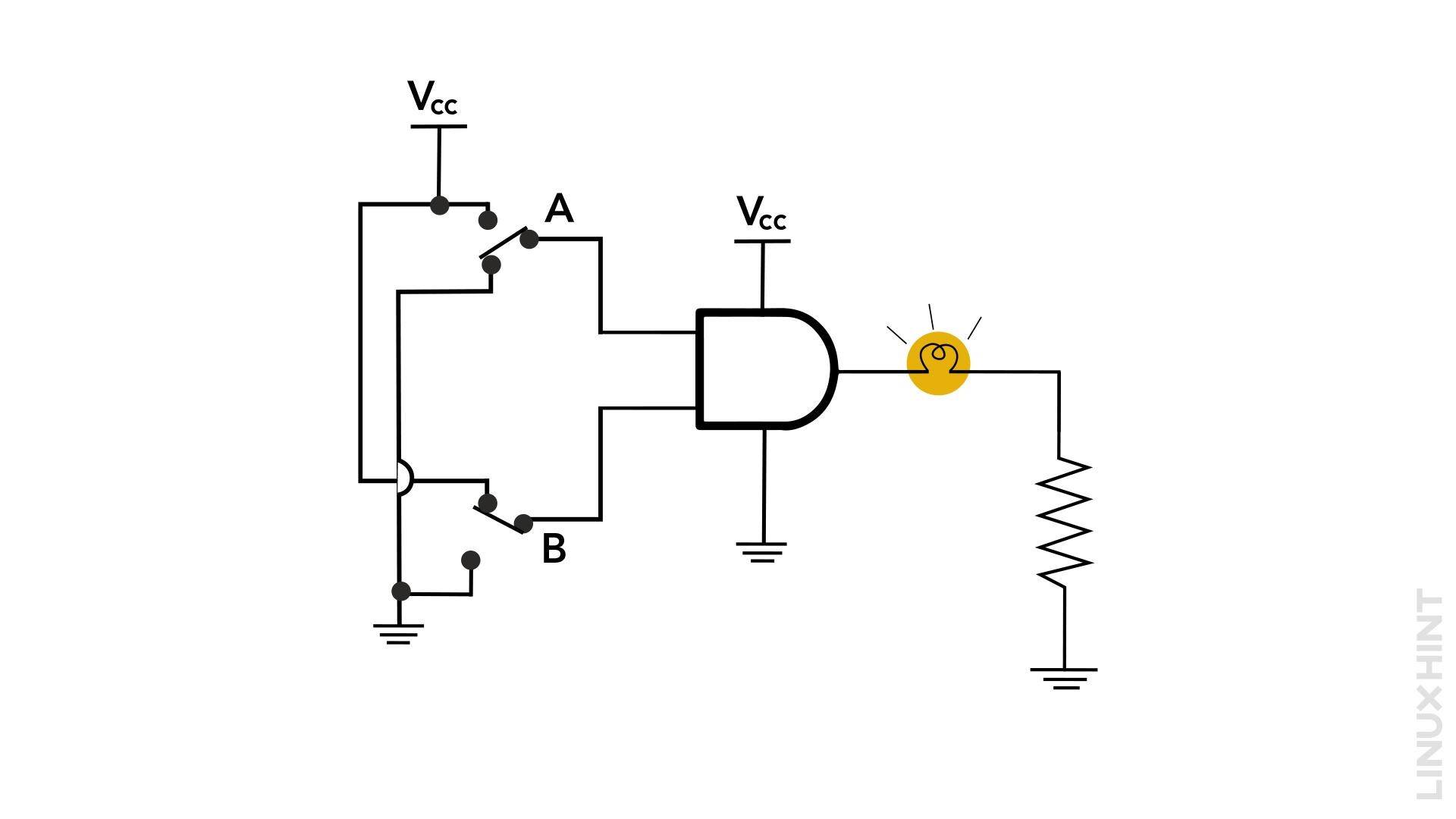
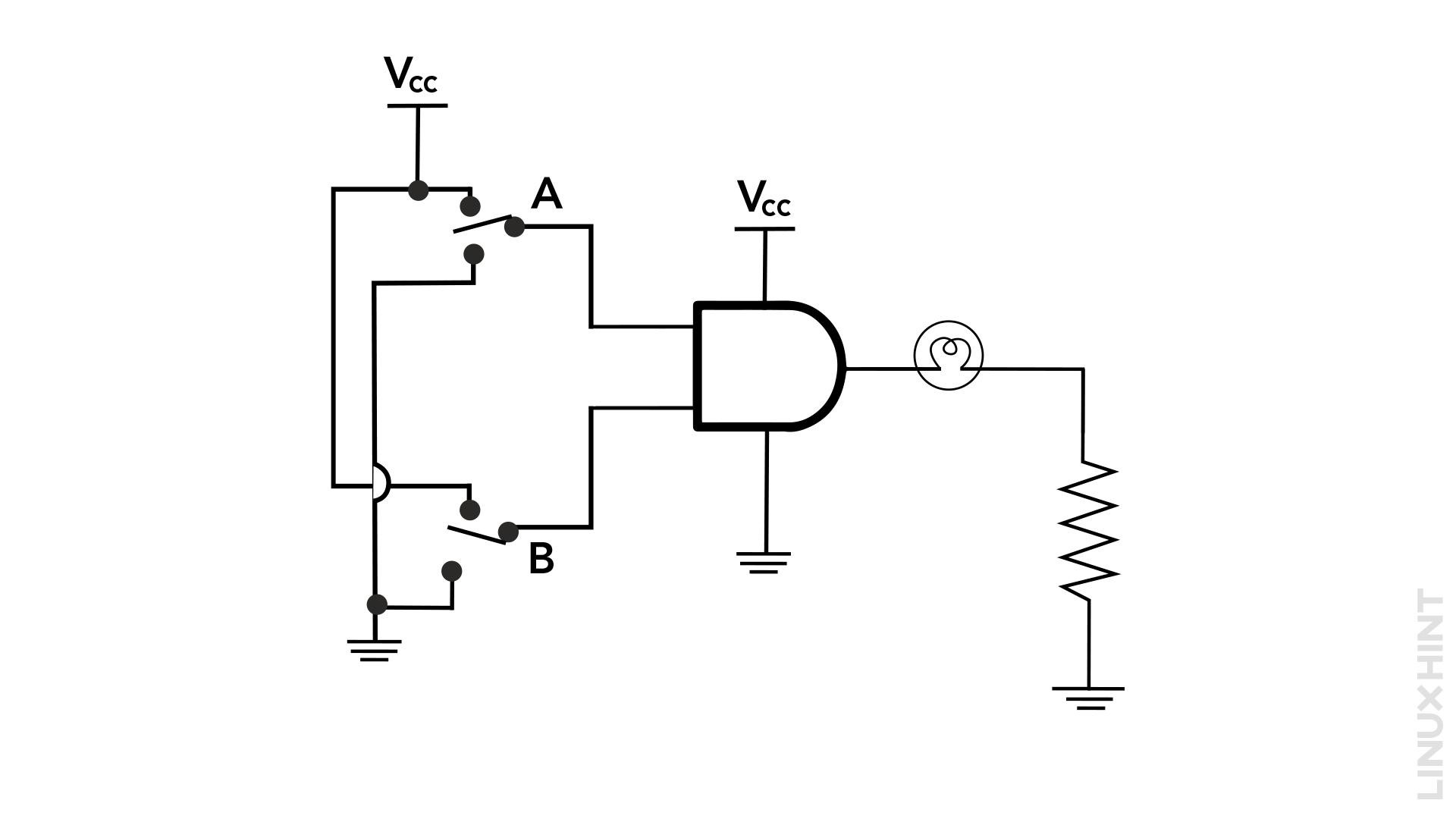
The operation logic of AND gate can be easily verified when its two inputs are connected with an external supply through on-off switches and the voltage at the output is monitored through an LED or fluorescent bulb as shown below:
The switches can now be closed at different combinations to monitor the operation logic. We will check all possible combinations of the voltage supply at the two inputs one by one below.
Case 1
When both of the inputs are off or low.
| Switch A | Switch B | Bulb (State) |
|---|---|---|
| Open | Open | Off |
The fluorescent bulb will not glow in this case.
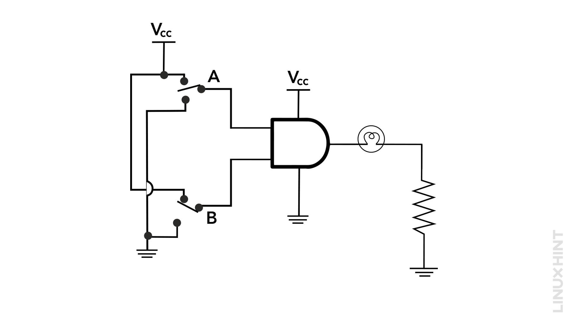
Case 2
When the first input is low/ zero and the second input is high/one.
| Switch A | Switch B | Bulb (State) |
|---|---|---|
| Open | close | Off |
The fluorescent bulb will not glow in this case.
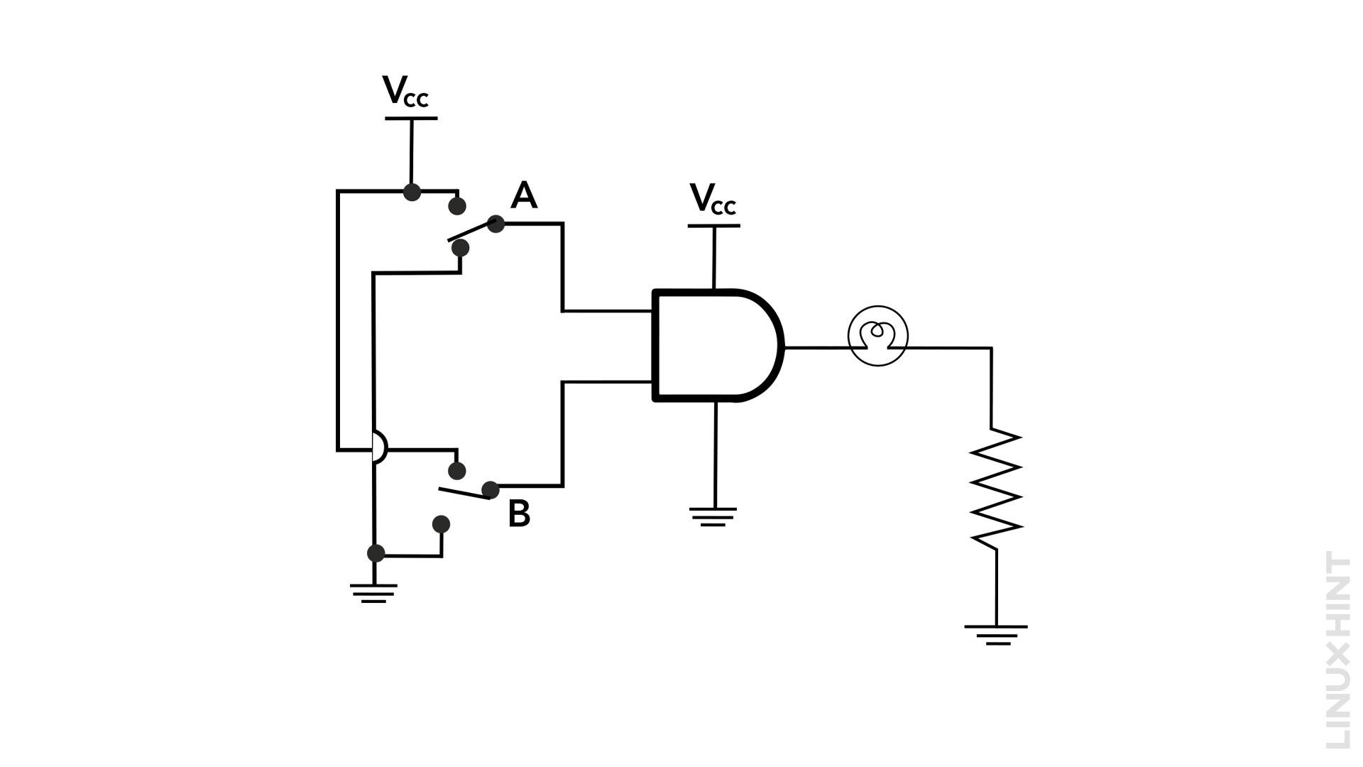
Case 3
When the first input is one/high and the second input is low/zero.
| Switch A | Switch B | Bulb (State) |
|---|---|---|
| close | open | Off |
The fluorescent bulb will not glow in this case.
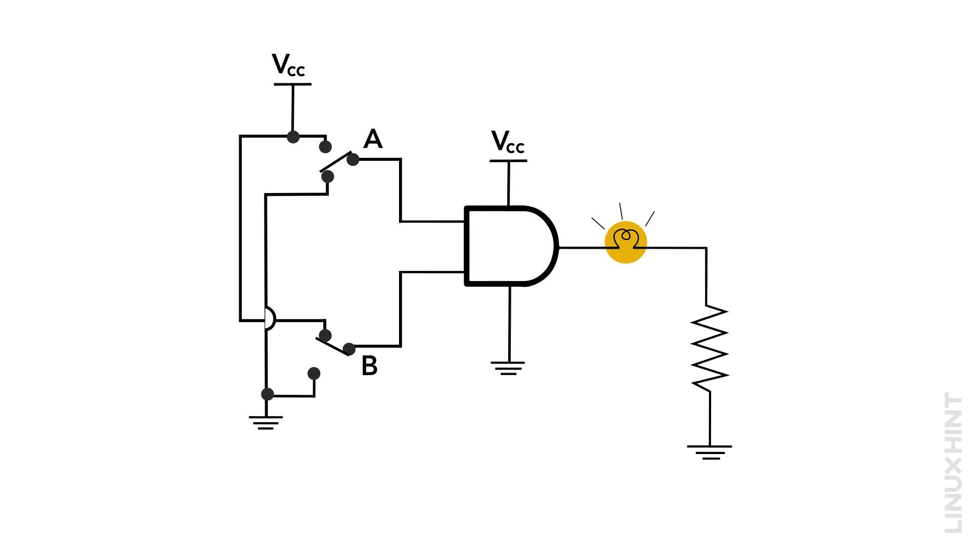
Case 4
When both first and second inputs are one/high.
| Switch A | Switch B | Bulb (State) |
|---|---|---|
| close | close | on |
The fluorescent bulb will glow in this case.
Conclusion
The operation logic of an AND gate is useful in a variety of digital electronics circuits, where the circuit is required to operate only when all the inputs achieve high states. The AND gate belongs to the basic logic gates family and employs the AND function, which means that it depends on each of the input states to generate the output.

