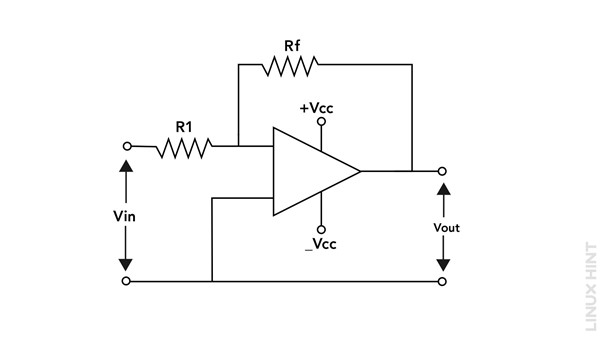
The Inverting Op-amp
The inverting op-amp is a configuration that uses an operational amplifier (op-amp) with negative feedback. As the input signal is applied to the op-amp’s inverting terminal (-), the device gets its name. To create a closed-loop setup, the output of the op-amp is then sent back to the inverting terminal by a feedback resistor (Rf).
Operating Principle
The inverting op-amp operates based on two essential principles: the virtual short concept and the virtual ground concept.
1. Virtual Short Concept
The voltage differential between an op-amp’s two input terminals should be almost zero (preferably zero) according to the virtual short principle. Consequently, the inverting terminal is maintained at virtual ground potential.
2. Virtual Ground Concept
The virtual ground concept states that the non-inverting terminal (+) of the op-amp is also at ground potential. This occurs because the op-amp has a very high input impedance, making the current entering the non-inverting terminal almost negligible.
By combining these two ideas, the inverting op-amp ensures that the voltage at the inverting terminal is nearly equivalent to the voltage at the non-inverting terminal, which is at ground potential.
Equations for inverting operational amplifier
The inverting op-amp can be analyzed using a few key equations:
1. Voltage Gain (Av)
The following formula can be used to calculate the inverting op-amp’s voltage gain, abbreviated as Av:
Where Rin is the input resistor attached to the inverting terminal and Rf is the feedback resistor, the negative symbol denotes a 180-degree phase shift between the input and output signals.
2. Input Impedance (Zin)
The input impedance of the inverting op-amp is primarily determined by the input resistor, Rin. The input impedance can be calculated as:
3. Output Voltage (Vo)
The equation below, where Vin is the input voltage applied to the inverting terminal, yields the output voltage of the inverting op-amp (Vo).
Significance in Electronics
Due to its distinct qualities, the inverting op-amp can be used in various applications:
1. Signal Amplification
The inverting op-amp is commonly used for signal amplification. By adjusting the feedback resistor, Rf, the gain can be precisely controlled. This allows for the amplification of weak signals and the generation of larger output signals.
2. Inverting and Non-inverting Summing Amplifiers
The inverting op-amp configuration can be extended to build summing amplifiers. By connecting multiple input resistors to the inverting terminal, the op-amp can sum the weighted input signals, providing a weighted sum at the output.
3. Active Filters
Inverting op-amps are extensively used in active filter designs. By incorporating capacitors and resistors in the feedback network, different types of filters, such as low-pass, high-pass, and band-pass filters, can be realized.
4. Voltage-to-Current Conversion
The inverting op-amp can also be employed as a voltage-to-current converter by connecting a resistor at the output terminal.
Conclusion
The inverting op-amp is a fundamental element in electronic circuits, enabling precise signal amplification, summing operations, and active filtering. By using its operating principles and equations, engineers can design and optimize circuits for various applications, driving innovation in the field of electronics.


