Interfacing LCD in 4-bit mode with Arduino
In the 4-bit mode the data sent to the display module from Arduino is in 4 bits similarly if the data is of 8 bits the data will be sent in the form of 4-4 bits that is data will be transferred using two pulses. This mode uses only four pins of Arduino.
In 4-bit mode the data sending speed is a little bit slow as the data is divided in 4 bits but still there is a negligible effect. The main advantage of using the 4-bit mode is that less pins of the Arduino are occupied, and the spares pins can be used for other purposes.
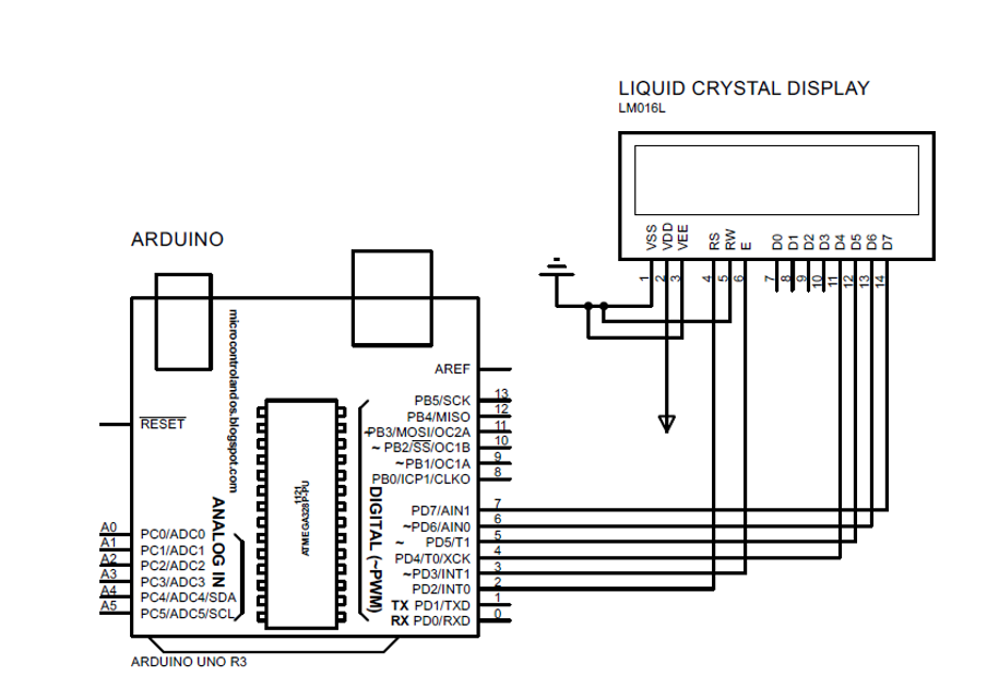
To further explain the interfacing of LCD in 4-bit mode we have taken an example in which a custom character is created and displayed on the LCD as well as a simple data is also displayed using the lcd.print() function. The Arduino program is also given in the context followed by the schematic diagram for interfacing the 4-bit LCD module and a simulation is created:
The Arduino code for 4-bit connection is:
LiquidCrystal lcd(2, 3, 4, 5, 6, 7);
unsigned char specialchar[8]={0x00,0x0A,0x00,0x00,0x11,0x0E,0x00};
void setup() {
lcd.begin(16,2);
lcd.clear();
lcd.createChar(0, specialchar);
}
void loop() {
lcd.setCursor(0,0);
lcd.print("Welcome");
lcd.setCursor(0,1);
lcd.print("To LINUX HINT");
lcd.write(byte(0));
}
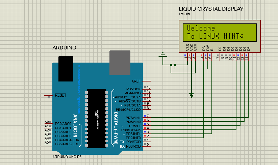
Simulation result would be:
Interfacing LCD in 8-bit mode with Arduino
When the LCD is interfaced in 8-bit mode all the data pins from D0 to D7 are connected to the Arduino. In this mode the data is transferred simultaneously as compared to the 4-bit mode as it uses only one pulse to send the data. Similarly, there are three control pins that are connected to the Arduino. This mode is comparatively fast as compared to the 4-bit mode this effect is negligible. The only drawback of the 8-bit mode is that it uses a lot of pins of the Arduino, and it is difficult to manage the pins for other tasks as well.
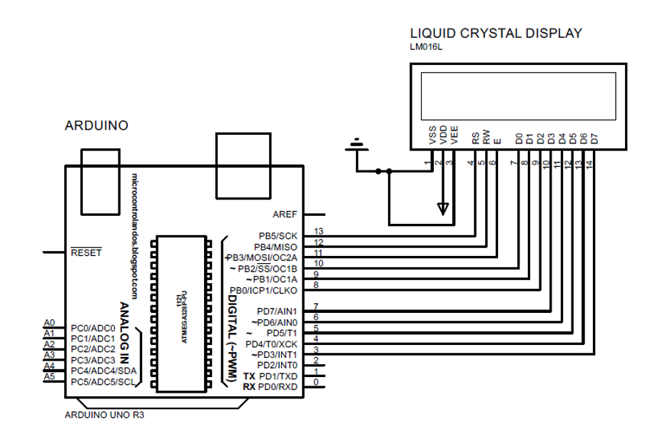
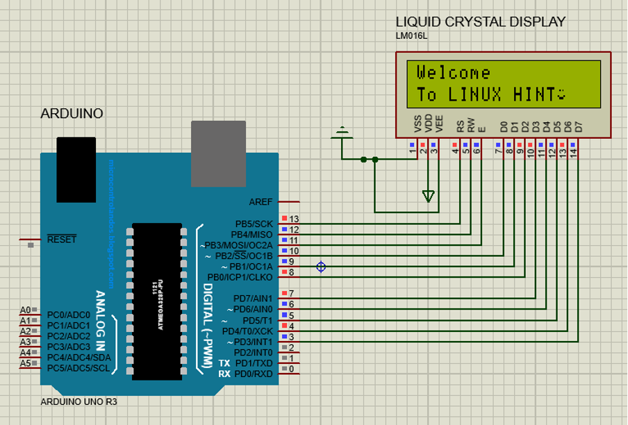
An example of using the 8-bit mode of the liquid crystal display is demonstrated using the simulator. It is the same example that was used in the case of interfacing the LCD in 4-bit mode. The Arduino program for the interfacing of LCD in 8-bit mode is given followed by the schematic of the circuit.
The Arduino code for 8-bit connection is:
LiquidCrystal lcd(13, 12, 11, 10, 9, 8, 7, 6, 5, 4, 3);
unsigned char specialchar[8]={0x00,0x0A,0x00,0x00,0x11,0x0E,0x00};
void setup() {
lcd.begin(16,2);
lcd.clear();
lcd.createChar(0, specialchar);
}
void loop() {
lcd.setCursor(0,0);
lcd.print("Welcome");
lcd.setCursor(0,1);
lcd.print("To LINUX HINT");
lcd.write(byte(0));
}
Simulation result is demonstrated below:
Conclusion
The liquid crystal displays (LCDs) are used with Arduino for displaying the output of the Arduino program. There are two modes in which the LCD can be interfaced with Arduino one is the 4-bit mode and the other is 8-bit mode. The major difference between the two is that the 8-bit used the 8 data pins of the display module whereas the 4-bit only used the 4 data pins and only used four data pins. The data transfer rate in 8-bit mode is greater than 4-bit mode.