What is an Operational Amplifier?
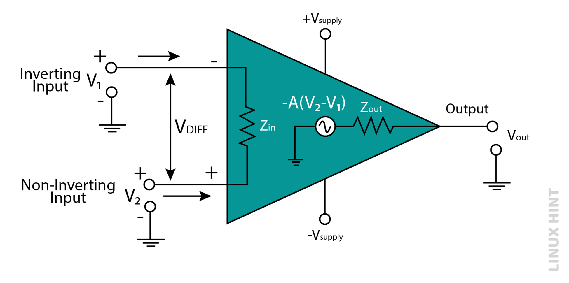
The operational amplifier is a three-terminal amplifier device comprising two inputs of a high impedance value and single output of low impedance value. One of the high impedance inputs is called non-inverting input and represented with ‘+’ sign while the other high impedance input is called inverting input and represented with ‘-’ sign.
Construction
An operational amplifier can have two different types of input terminals: inverting & non-inverting terminals. Inverting terminal is denoted with ‘-’ sign and non-inverting terminal is denoted with ‘+’ sign. Positive terminal of DC source is connected to non-inverting terminal of op-amp and negative terminal of DC source is connected to inverting terminal of op-amp.
A common terminal of the op-amp is connected to ground or with a reference point.
Working Principle
Op-amps work in amplification modes in a variety of their configurations. The working principle of amplification of operational amplifiers can be mainly divided as per the two types of their gains: with or without feedback. The open loop gain applies to non- feedback-based op-amps configurations and closed loop gain applies to feedback- based op-amp configurations.
Open Loop Configuration
The open-loop configuration of an op-amp does not involve any feedback and is therefore called an open-loop.
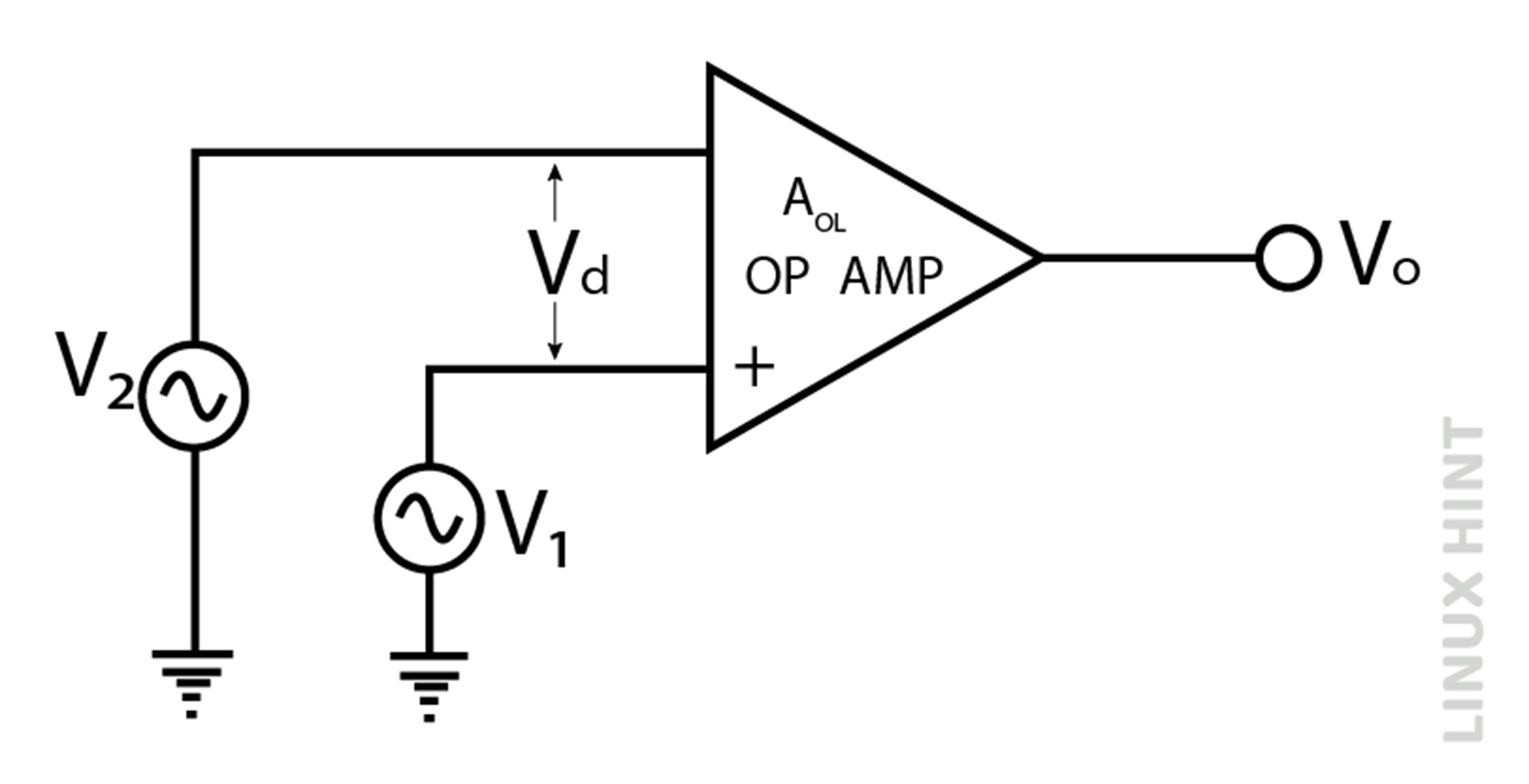
The output voltage in open loops is expressed as:

The presence of open loop gain Aol acts as an amplification factor, V+ is input voltage at non-inverting terminal and V– is input voltage at inverting terminal while VD is difference of voltages(V+ – V– ) at the two terminals. The output is therefore an amplified version of the difference of magnitude of two input signals.
Closed Loop Configuration
Op-amps configurations that include feedback paths are called closed loop op-amps. A feedback path connects output back to the input.
Therefore, an input of an op-amp receives two types of signals in feedback mode: one the actual input and one the feedback input from the output. The output voltage for closed loop op-amp is given by:

Closed loop gain is denoted by Acl, V+ is input voltage at non-inverting terminal and V– is input voltage at inverting terminal.
Parameters
Operational amplifiers have a variety of parameters that determine its operation, output efficiency and limitations. These are briefly explained below:
Open Loop Gain, Aol
Open loop gain can be understood as the efficiency of operation for an operational amplifier. It is the ratio of two voltages; output voltage to input voltage. The term ‘open loop’ is used to define the absence of a feedback path. Ideally the value of open loop gain is infinite, but values fall in ranges of 20,000 up to 200,000.
Input Impedance, Zin
Input impedance is the measure of opposition offered to flow of current at the input terminal of an op-amp. Ideally, the input impedance of an op-amp is extremely high to prevent any flow of current into the terminals.
Output Impedance, Zout
Output impedance is the measure of opposition offered to flow of current at the output terminal. It is ideally zero.
Input Offset Voltage
It is the magnitude of voltage applied at inverting and non-inverting terminals to obtain a zero output.
Input Offset Current
It is the difference in magnitude of currents between their two terminals: the inverting and non-inverting terminals of the operational amplifier.
Bandwidth
Op-amp can convert any DC signal into the highest frequencies-based AC signals. In the case of ideal op-amps, the bandwidth is infinite. In practical cases, bandwidth is found by the product of gain and bandwidth.
Slew Rate
It is the maximum rate of change in output voltage with respect to step input voltage. The slew rate of the operational amplifier will increase with increase in the magnitude of supply voltage and the closed loop gain. However, its value decreases with an increase in temperature.
Types of Operational Amplifier
Op-amps can be divided into many types. Some of the major classifications are briefly described below:
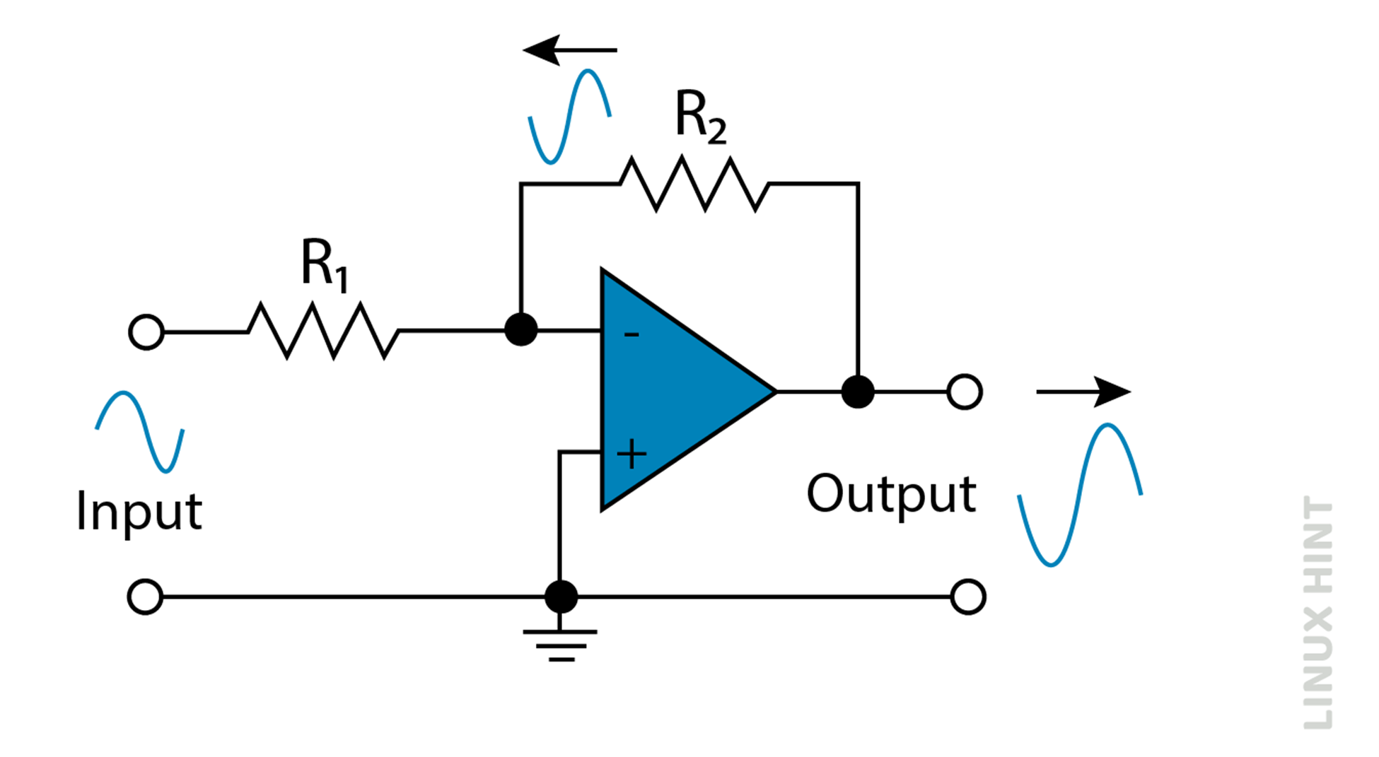
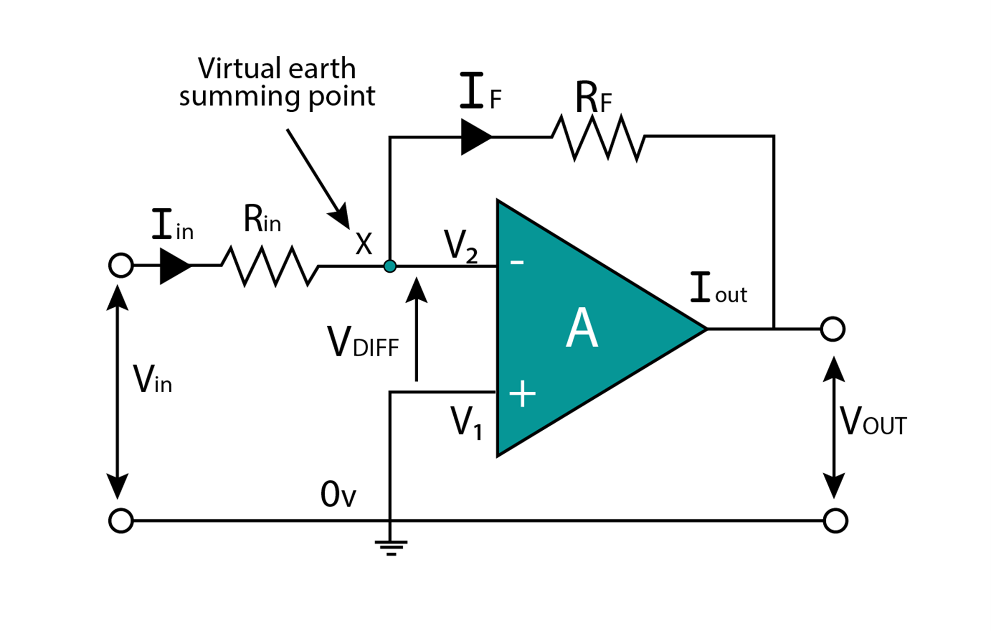
Inverting Op-Amp
The inverting operational amplifier receives input at the inverting terminal while its non-inverting terminal is connected to the ground or reference point. It is called inverting op-amp configuration.
The output voltage in inverting op-amp configuration is given by expression:

Non-Inverting Op-Amp
The non-inverting operational amplifier receives input at the non-inverting terminal while its inverting terminal is connected to ground or reference point. It is called non-inverting op-amp configuration.
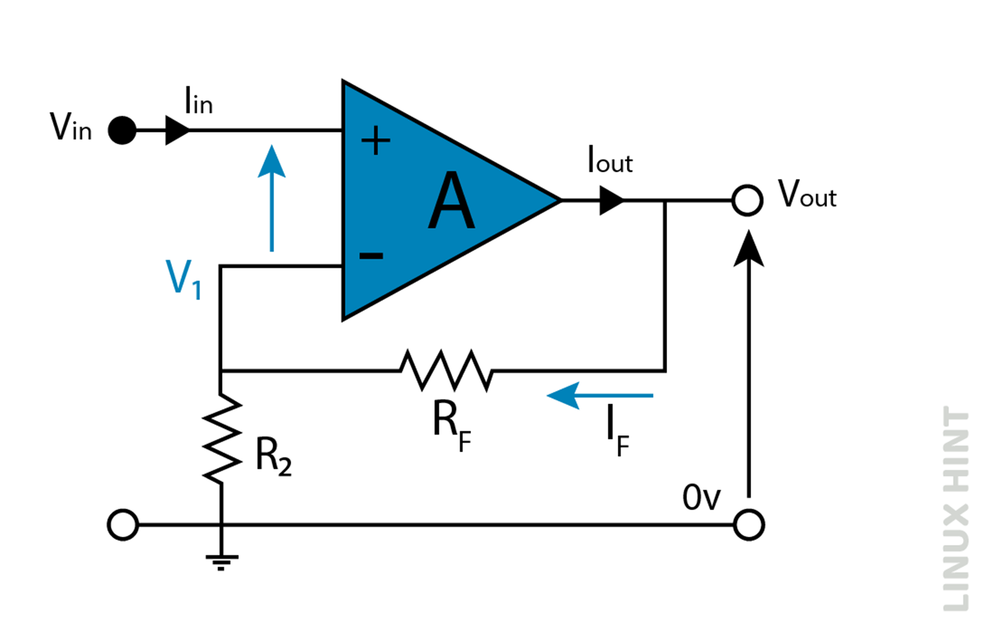
The output voltage in inverting op-amp configuration is given by expression:

Differential Op-Amp
Differential operational amplifiers amplify the difference in voltage of two input signals. Two different input signals are applied at inverting and non-inverting terminals.
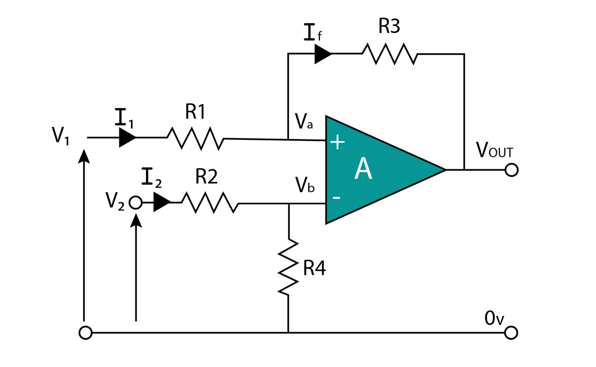
The output voltage in differential op-amp configuration is given by expression:

If all of the resistances are same, then the above expression reduces to:

The above expression shows unity gain and therefore when resistances in differential amplifiers are the same, a unity gain differential amplifier is obtained. It is due to the reason this arrangement is also called voltage subtractor configuration.
It can also be noted that in differential amplifiers if V1 is greater than V2 , the output voltage Vout is negative and if V2 is greater than V1, positive output voltage shall be obtained.
Integrator Op-Amp
It is an inverting amplifier configuration with the addition of feedback capacitors. It provides an integrated version of input voltage at its output terminal.
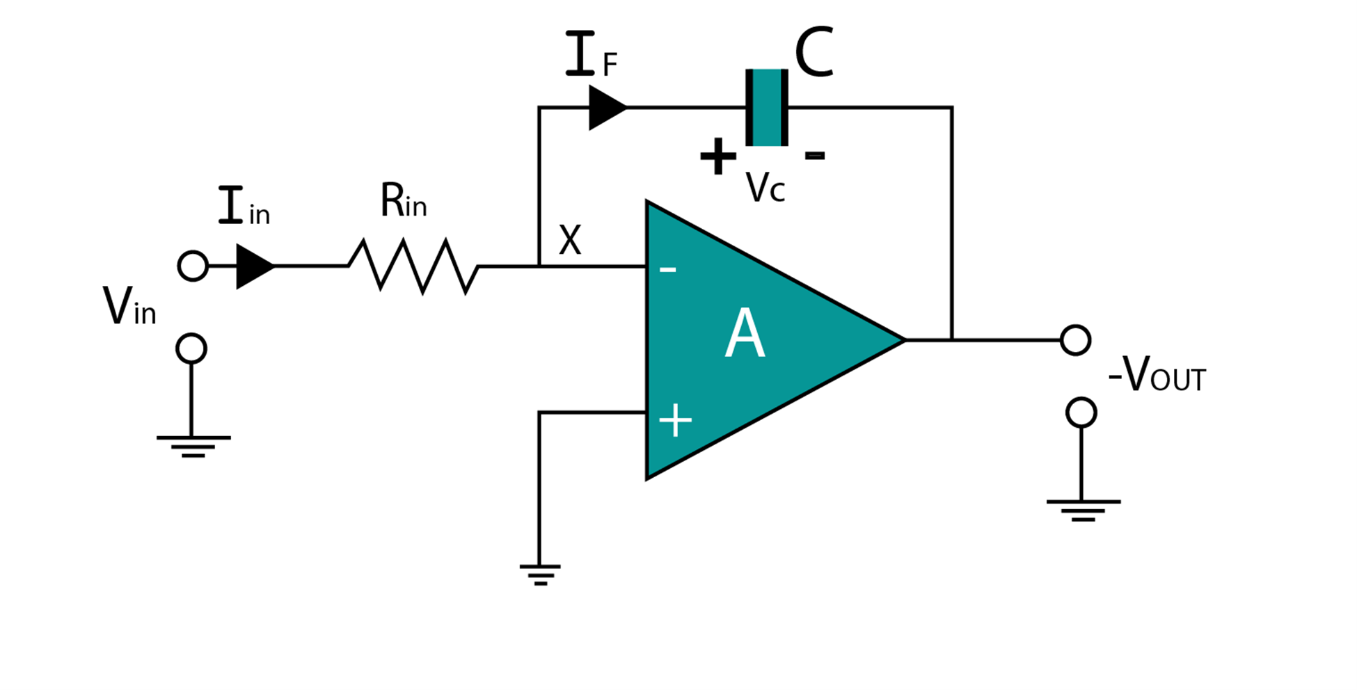
The output voltage in integrator op-amp configuration is given by expression:

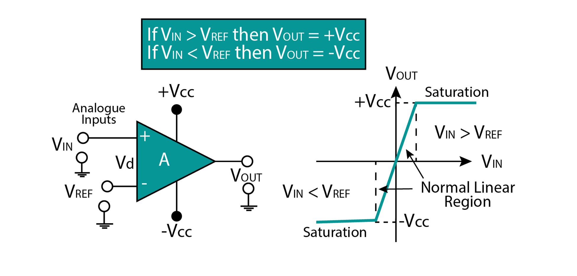
Comparator Op-Amp
It compares the magnitude of two voltages at its two inputs and provides an output based on which input voltage is greater than the other. One of the voltages acts as a reference while the input signal is applied at the other.

In the above configuration, input voltage is applied at an inverting input terminal while non-inverting acts
as a reference, it is called inverting comparator configuration. Similarly, if input voltage is applied at a non-inverting terminal, it is called non-inverting comparator configuration.
Below figures show a case of non-inverting comparator configuration. The output voltage will appear as Vout=+Vcc if Vin>Vref. Similarly, output voltage will appear as Vout=-Vcc if Vin<Vref as shown below:
Conclusion
Operational amplifiers come in a variety of different configurations. They are used in every electronic circuit for purposes of amplification, addition, comparison, and integration.