Hall Effect Sensor
Hall effect sensors detect the magnetic field strength and direction of a permanent magnet or electromagnet. The hall effect sensor output is a function of its magnetic field and can detect positive as well as negative magnetic fields.
Working Principle of Hall Effect Sensor
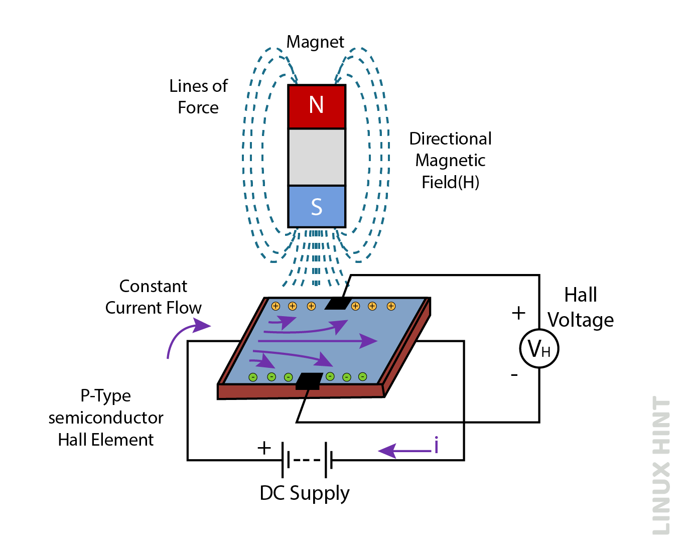
An external magnetic field activates hall effect sensors. Magnetic fields are represented with flux density (B) and by its magnetic poles, such as either north pole or South Pole. The magnetism around the hall effect sensor determines its output signal. When the ambient magnetic flux density exceeds a predetermined threshold value, the sensor produces a Hall voltage, VH.
Semiconductor sensors are p-type semiconductors such as gallium arsenide (GaAs), indium arsenide (InAs) and indium antimonide (InSb) that conduct direct current. The semiconductor material experiences a force in presence of magnetic field, causing both electrons as well as holes to move to sides of the semiconductor layer. As electrons and holes move to either side, a potential difference is developed between the different sides of the semiconductors. In flat rectangular materials, an external magnetic field perpendicular to the semiconductor material has a greater effect on electron mobility.
The hall effect shows the magnetic pole type and its field strength. For example, there is a voltage at one of the magnet’s poles, but not at the other one. Hall effect sensors are usually “off” and act like an open circuit when there is no magnetic field. They are closed only under a strongly polarized magnetic field (closed circuit).
Hall Effect Magnetic Sensor Characteristics
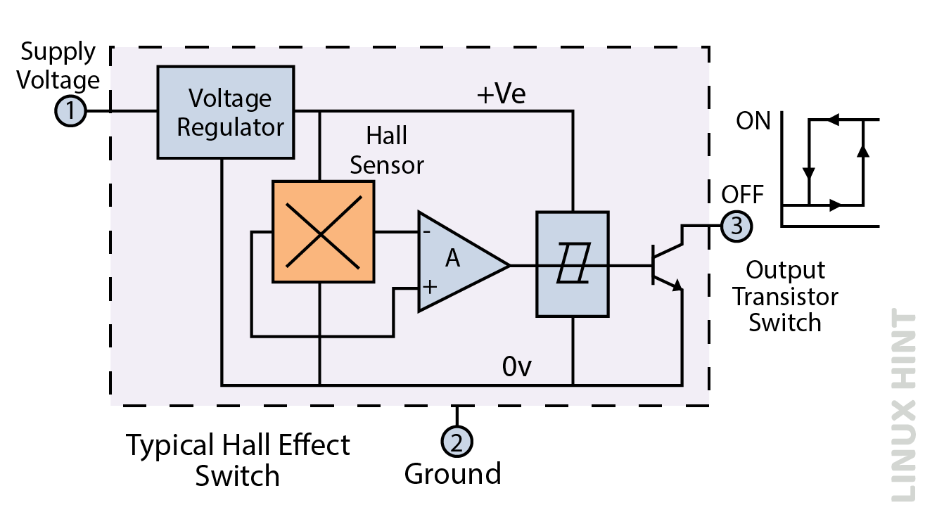
The hall voltage (VH) of the hall effect sensor is a function of its magnetic field strength (H). Most commercial hall effect devices include DC amplifiers, switching logic circuits, and voltage regulators in them to improve sensor sensitivity and output voltages. This allows the hall effect sensor to handle more power and magnetic fields.
Hall Effect Magnetic Sensor Circuit Diagram
The semi-active sensors have linear or digital outputs. The output voltage of the linear sensor relates directly to the magnetic field flowing through the hall sensor and is output by an operational amplifier.
Hall Effect Voltage Equation
The output voltage equation is given by:
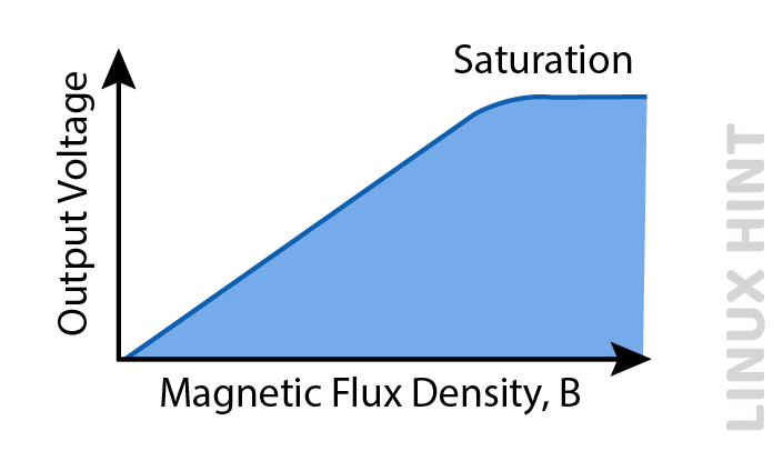
Here, VH denotes the hall voltage, RH denotes the hall effect coefficient, I denote the current, t denotes the thickness and B stands for the magnetic flux density. Linear or analog sensors produce a constant voltage that increases with stronger magnetic fields and decreases with weaker fields. In a hall-effect sensor, as the strength of the magnetic field increases, the output signal of the amplifier increases until the power supply saturates. Increasing the magnetic field causes the output to saturate but has no effect:
When the hall sensor’s output exceeds a predetermined level of magnetic flux flowing through it, the contacts switch quickly from the “closed” state to the “open” state without bouncing. This built-in hysteresis prevents the output signal from oscillating as the sensor moves into the magnetic field. This means that the digital output sensor only has “on” and “off” states.
Hall Effect Sensor Types
Hall effect sensors can be of two types: bipolar hall effect sensors and unipolar hall effect sensors. Unipolar sensors can operate and discharge when entering and exiting a magnetic field with the same south magnetic pole, while bipolar sensors require both positive and negative magnetic fields to operate and discharge. Due to their 10-20mA output drive capabilities, most hall effect devices cannot directly switch high current loads. For heavy current loads, an NPN transistor is added to the output with an open collector arrangement.
Applications of the Hall Effect Sensors
The hall effect sensors are switched ON in the presence of magnetic fields and they are controlled by a single permanent type of magnet on a moving shaft or gadget. To maximize sensitivity, the magnetic flux lines must be perpendicular to the sensor field and with the correct polarization in all configurations.
1: Head on Detection
It requires the magnetic field to be perpendicular to the hall effect detector, as shown below:
This technique produces an output signal, VH, that measures the magnetic flux density in linear devices as a function of distance from the hall effect sensor. The output voltage increases with the magnetic field’s strength and its proximity.
2: Sideways Detection
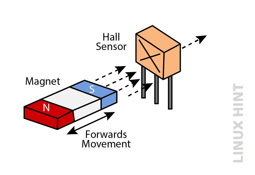
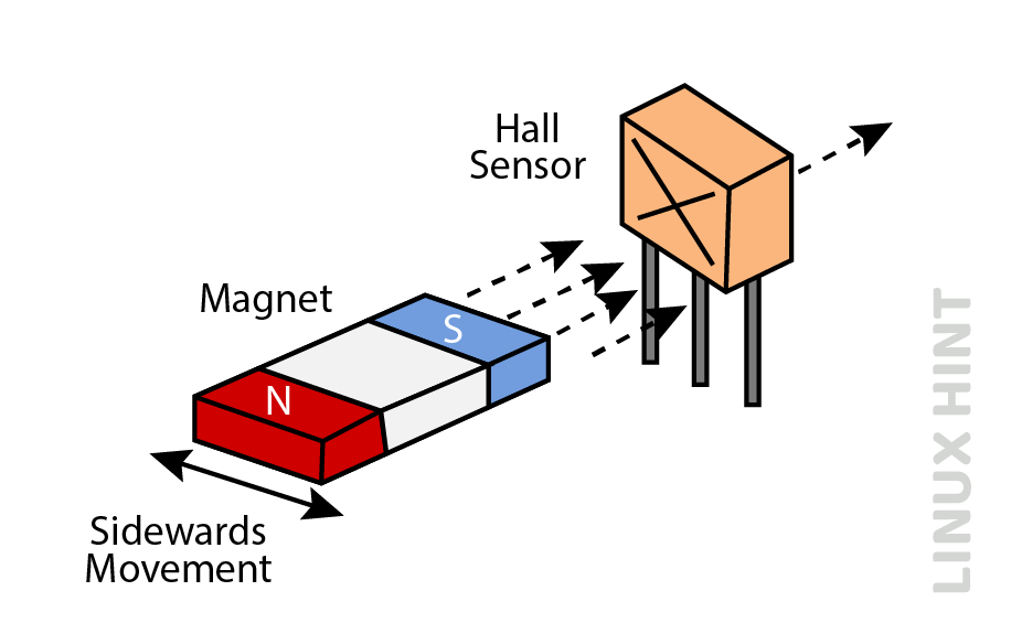
It requires an indirect magnetic flux while the magnet moves sideways across the hall effect element.
Lateral or movable sensors can measure the speed of rotating magnets or motors by detecting the magnetic field sliding on the surface of the Hall element at a certain distance from the air gap.
A positive or negative linear output voltage can be produced depending on the position of the magnetic field passing through the sensor’s zero-field centerline. It determines vertical and horizontal movements.
3: Position Control
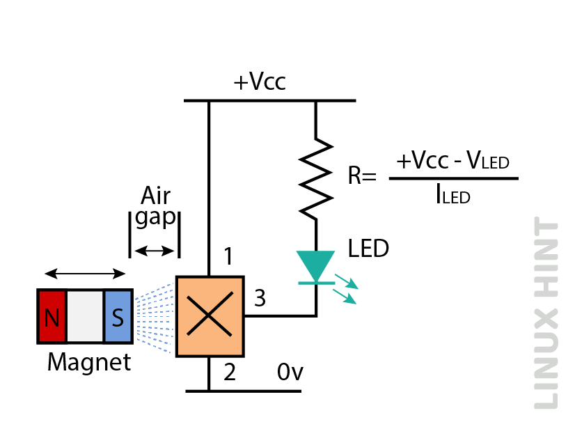
The position detector remains in the “off” state when there is no magnetic field. As soon as the magnet’s south pole moves in a perpendicular direction to the vicinity of the hall effect sensor, the device switches “on” and the LED glows. When powered on, the hall effect sensor is in the “ON” state.
To turn off the LED, the magnetic field must drop below its minimum detectable triggering point, or it can also be confronted with the opposite north pole with negative gauss value.
Conclusion
The hall effect sensors are used for detection of direction as well as the strength of magnetic fields. They are used in a wide variety of applications including automotive, proximity sensing, head on, sideways and position detections for different magnetic fields.

