Grounding
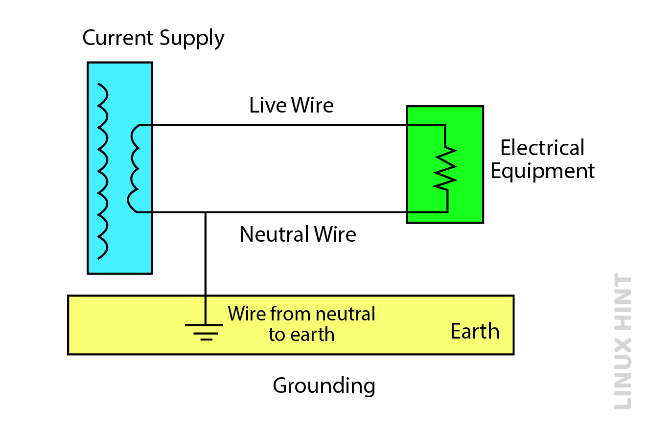
In grounding, the main current carrying wire is connected to the ground directly and provides the return path for the leakage current and prevents equipment from damage.
Whenever a fault occurs in the system, an unbalanced current pass through all three phases of the circuit. The grounding provides great safety to equipment and discharges the unbalanced current.
Working of Grounding
An electrical system depends upon the negative and positive electrical connection. These connections provide the device or equipment with the power needed to operate. But whenever any fault occurs in the electrical system or in the equipment, the excess power is stored in the electrical connections and in the equipment, which causes an electrical shock on touching it.
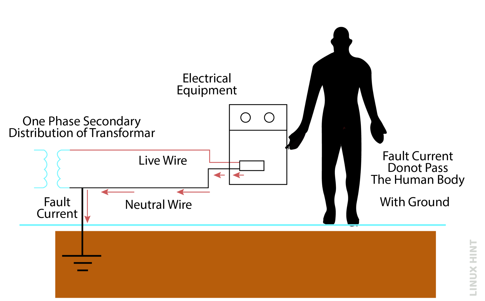
The grounding wire will take that excessive power and send it directly to the ground. It is a connection where the electricity can easily and safely discharge without harming the appliances.
Purpose of Grounding
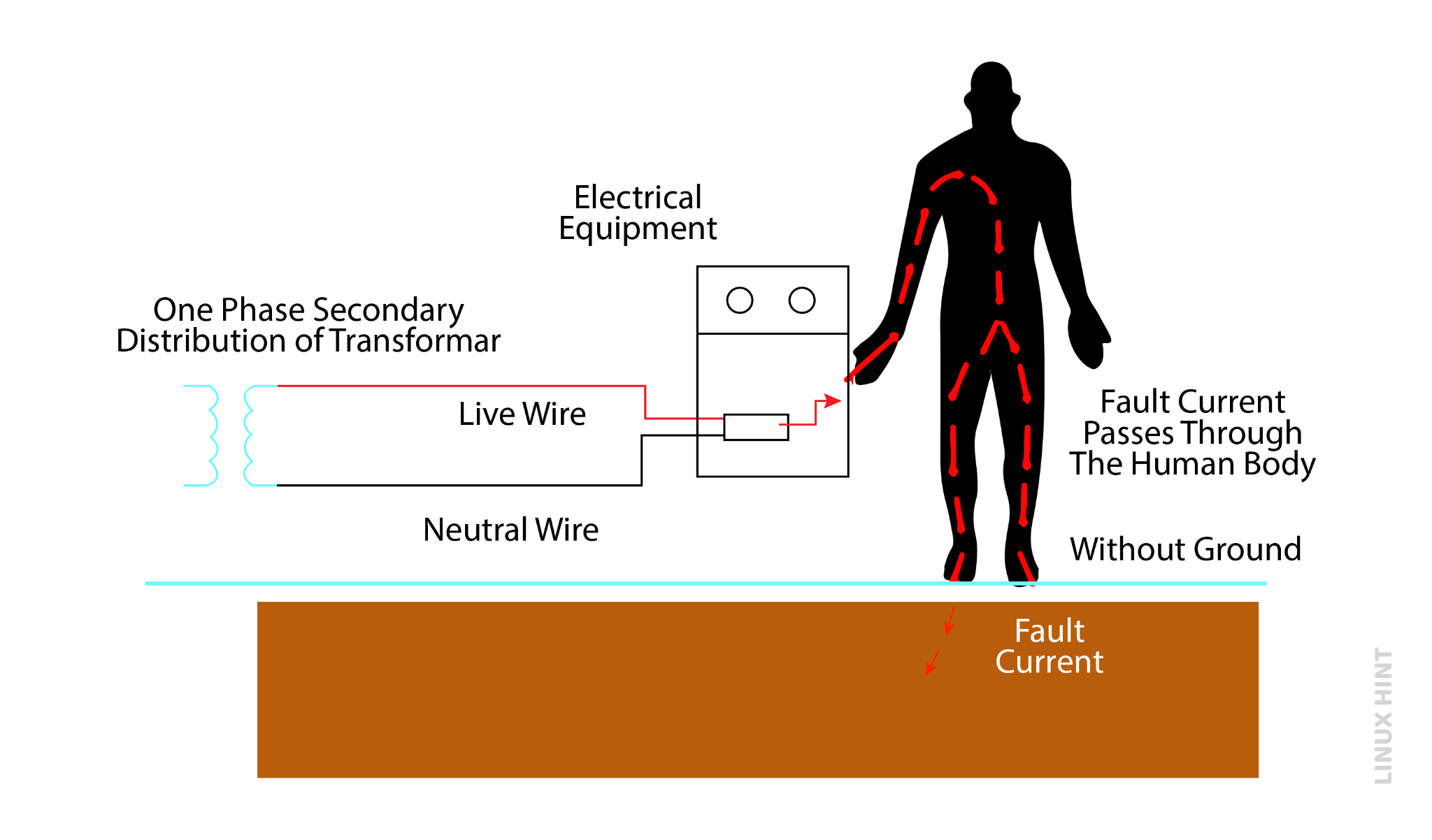
Grounding is used for the protection of electrical equipment and the user. In a workplace, workers are at high risk whenever a short circuit happens, and electrical devices discharge excess electrical energy.
Without having proper grounding, the excess electrical energy or power will transfer from the worker to the ground and find a pathway to discharge on touching the device, it leads to a serious shock and injury to the worker and sometimes leads to death:
Types of Grounding
There are five types of grounding, depending upon how we ground the electrical system.
Underground System Grounding
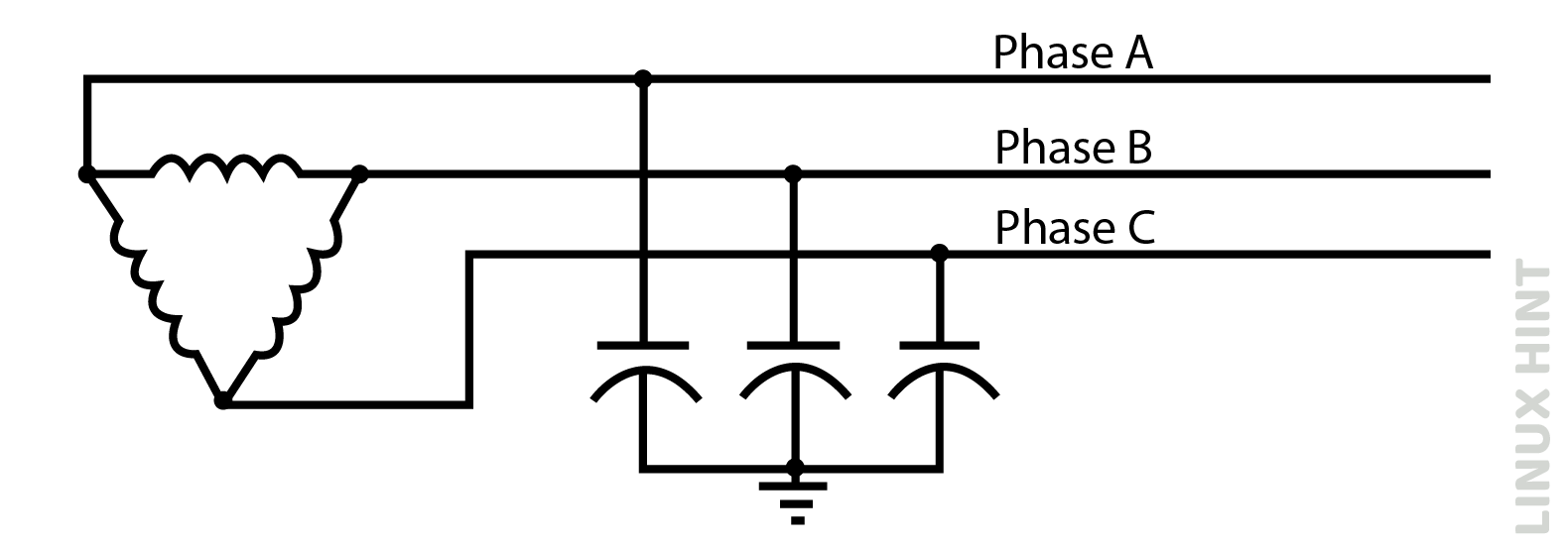
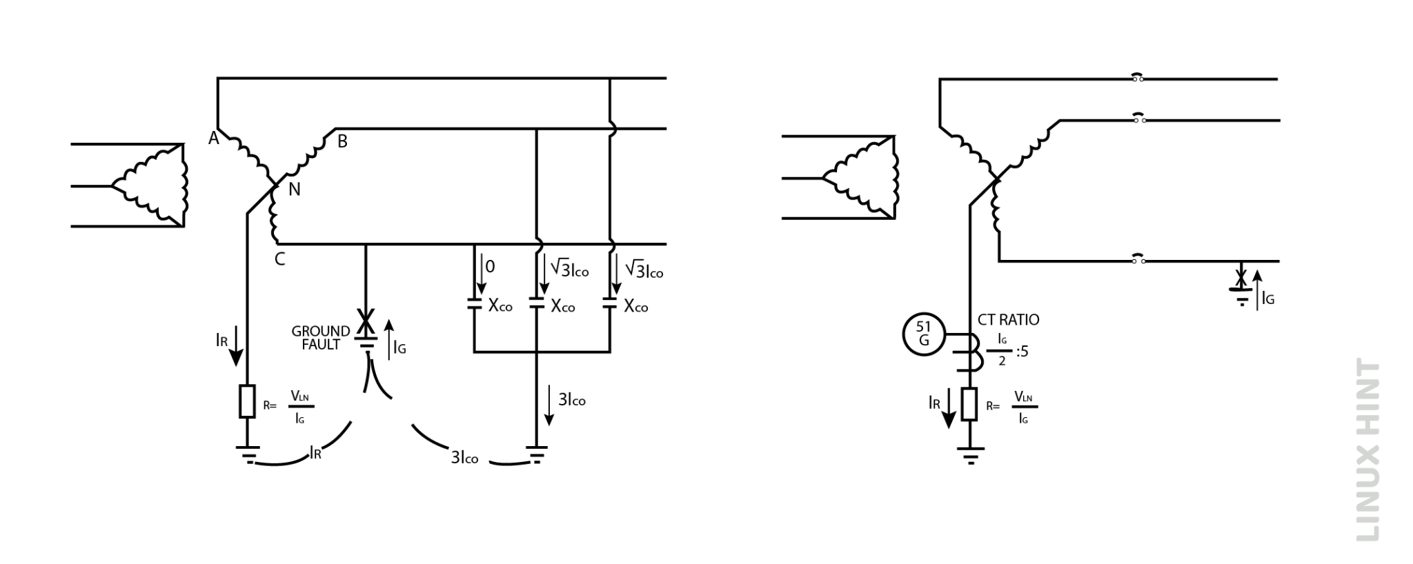
Underground grounding is done by connecting a capacitor between the ground and the circuit. We can name it as “Capacitance grounding”. We just call it underground by convention, as there is not a direct physical connection between the power lines and the ground.
Resistance Grounding
In this type of grounding, we have a connection between our neutral line and ground through a resistor. This resistor limits the fault current through our neutral lines. If there is no change in the voltage, the current depends on the size of the resistor by “ohm’s law” that is V=IR. Resistance grounding are of the following types:
Low Resistance Grounding
The neutral and the ground are connected by a very low resistance. The low resistance grounding limits the flow of current tom ground 100A to 1000A, The value of this connected low resistance can be calculated by,
Here:
VL is potential difference between ground and neutral
IG is the current guided to the ground
When any fault occurs in the circuit, line voltage raised by neutral voltage and current start flowing through ground resistor. In low resistance grounding, the ground fault can easily detect by overcome relay. The relay will open the circuit breaker if the incoming current is greater to the actual value of the desire current.
High Resistance grounding
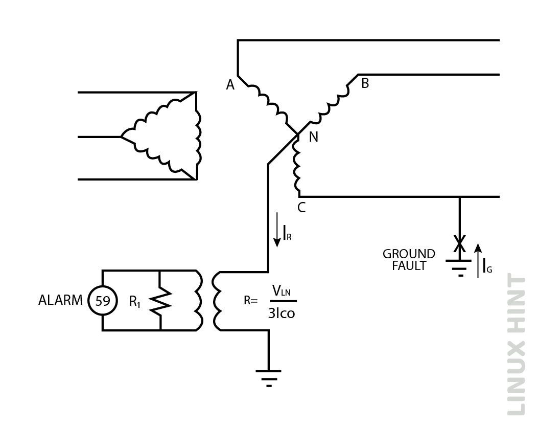
High resistance grounding is done by connecting a high resistance between the ground and the neutral. This high resistance limits the flow of current to the ground to 10A or less.
In high resistance grounding, the system continues to operate even if there is any fault present in the system. If any faults occur in the system, the neutral voltage is raised to the phase voltage and detected by an overvoltage relay and generate the alarm.
Solid grounding
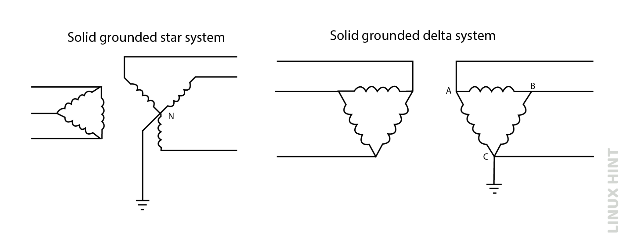
In solid grounding, there is a direct connection between the neutral line of the circuit and the ground. The ground is connected to the neutral terminal, similar to the neutral terminal of the generator and the transformer.
Reactance Grounding
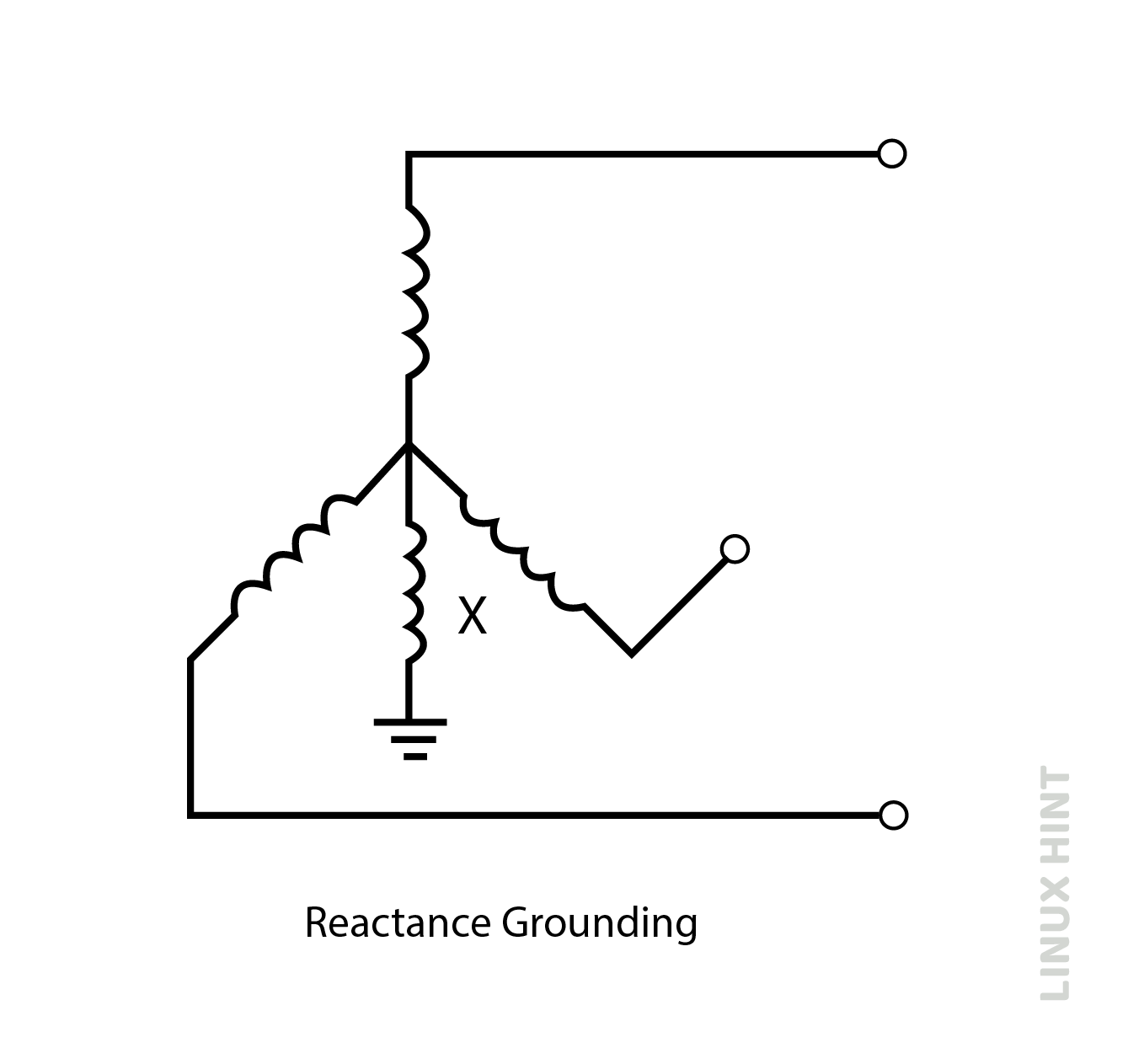
Inductive reactance in an inductor opposes the flow of the current through it. In reactance grounding, fault current is limited by connecting an inductor between ground and neutral. The value of reactance used in reactance grounding should never be too small or too large. Its value should not be less than the 26% of the three-phase fault current.to minimize the value of transient over voltage.
Difference Between Earthing and Grounding
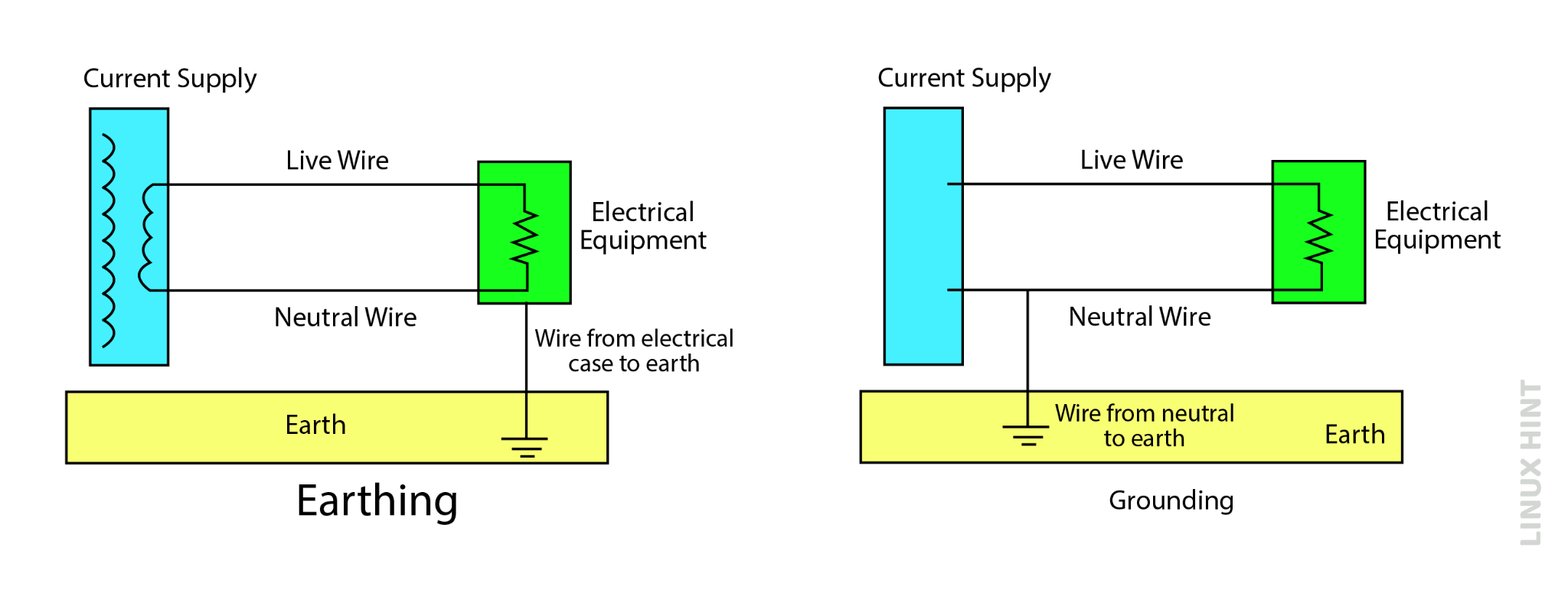
Earthing and ground are not the same in engineering. The key difference between the earthing and grounding is that, in earthing, there is a direct connection between the appliance and the ground to neutralize the excess voltage appearing on the appliance.
But in grounding, the appliance is not connected to the ground; instead, the negative terminal of the power supply is connected to the ground which will carry excess power or current during any fault in the electrical system and neutralize the whole system and the appliance.
| Grounding | Earthing |
| The neutral wire of the power supply connected to the ground. | The appliance is connected directly with the ground. |
| It protects the whole electrical circuit and the appliance. | It protects human body on touching the appliance. |
| It is used to balance the voltage when the circuit is overloaded. | It is used to avoid dangerous electrical shocks and lightning strikes to buildings. |
| No need of underground construction. | A conducting material is driven down to the earth. |
Conclusion
Grounding systems are commonly used and designed to protect against any danger of high-voltage discharges by removing the excess current flow. When any fault occurs in the electrical system or in the equipment, the excess power is stored in the electrical connections and in the equipment, which causes an electrical shock on touching it.

