What is a Full Wave Rectifier
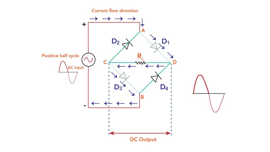
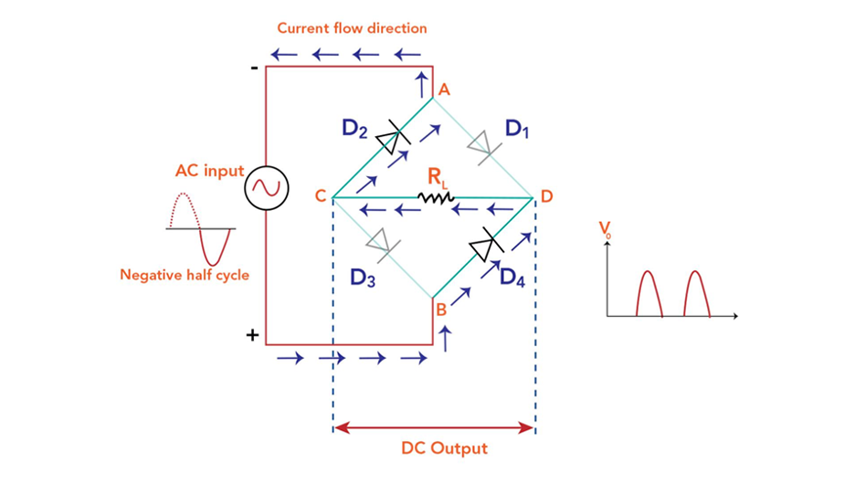
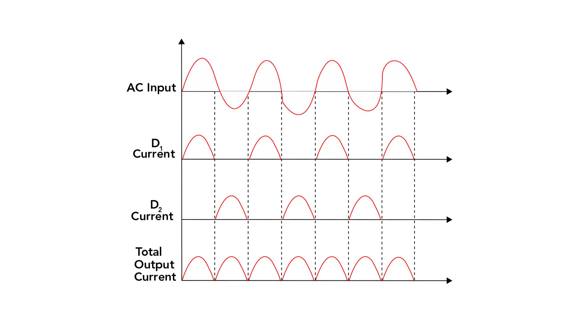
A full wave bridge rectifier is a circuit design that converts AC electricity into DC voltage. Unlike the half-wave rectifier, which utilizes only half of the input AC waveform, the full-wave bridge rectifier takes advantage of the complete AC cycle, resulting in a more efficient and smoother DC output.
Construction of a Full Wave Rectifier
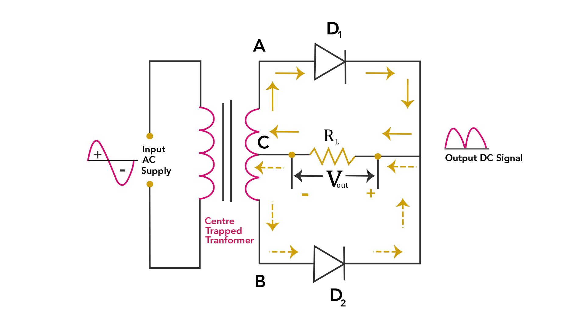
A full-wave rectifier can be constructed using diodes and a center-tapped transformer, the basic components include:
Center-tapped transformer: It provides the AC input to the rectifier, and the center tap allows for the creation of two equal but opposite voltages.
Two diodes: These diodes allow only one direction of current flow and are attached to the transformer’s secondary winding.
Load Resistor: The bridge rectifier’s output terminals are linked in parallel with a load resistor as the rectified DC voltage is used by it.
Full Wave Bridge Rectifier Working Principle
The operation of a full-wave rectifier can be divided into two half-cycles: the positive half-cycle and the negative half-cycle. By performing the following actions, a full wave bridge rectifier’s operation can be understood:
1. Positive Half-Cycle
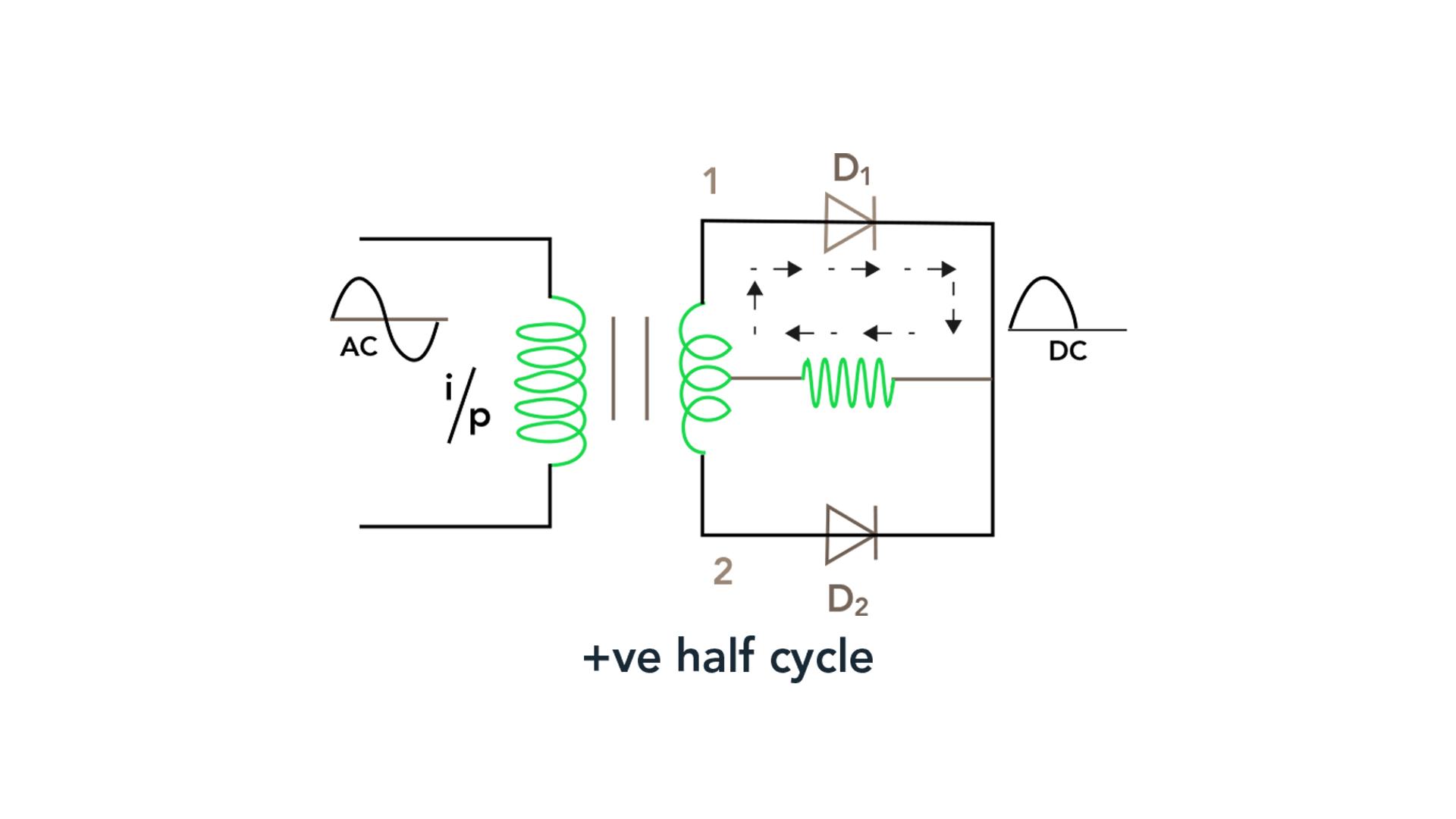
The upper end of the secondary winding becomes positive concerning the transformer’s center tap during the positive half-cycle of the input AC signal. When diode D1 is forward biased, current can pass through it and D2 becomes reverse biased and stops conducting at the same moment. Positive voltage is produced across the load as a result of the forward flow of current through the load resistance.
2. Negative Half-Cycle
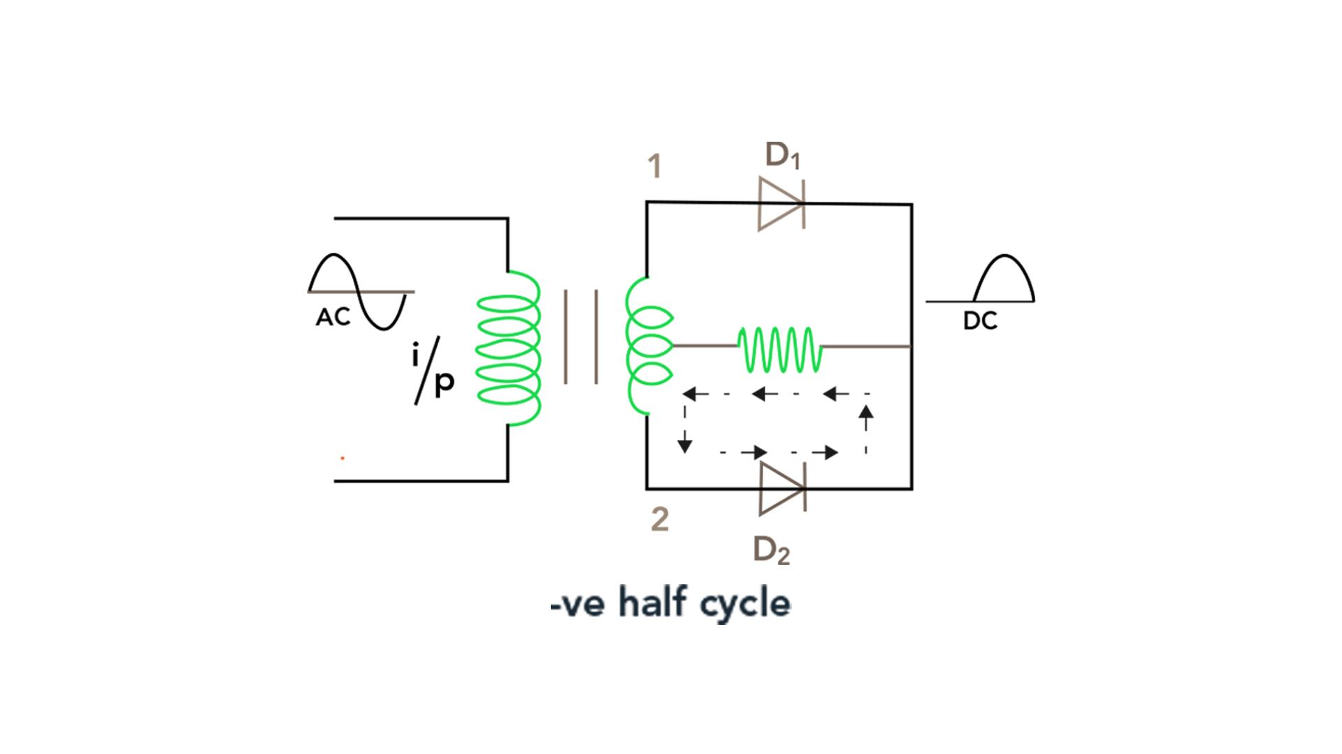
The upper end of the secondary winding turns negative with respect to the center tap during the negative half-cycle of the input AC signal. While diode D2 becomes forward-biased and permits current to flow, diode D1 becomes reverse-biased and ceases to conduct. The current passes through the load resistance similar to the positive half-cycle but in the opposite direction. Additionally, a positive voltage across the load is produced by this.
3. Overall Output
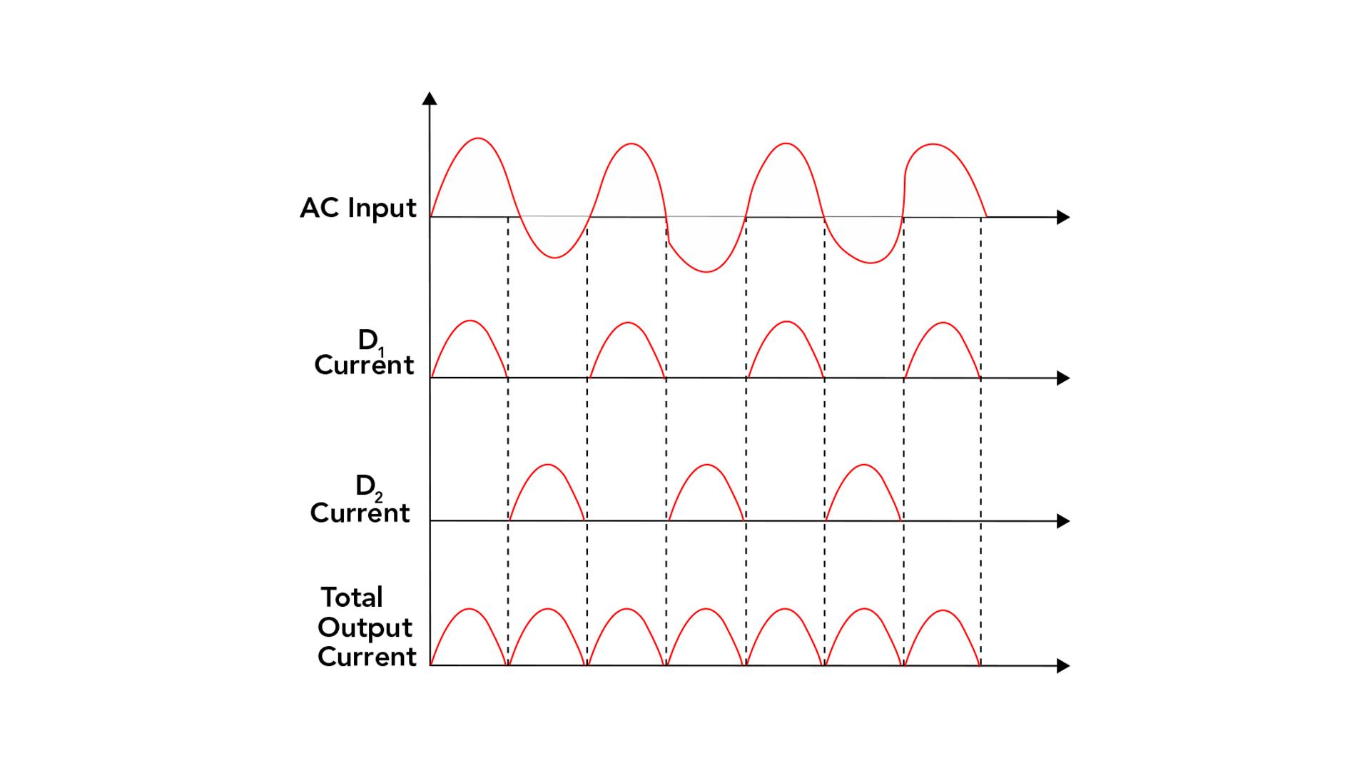
As a result, the load resistance transforms the AC input’s positive and negative half-cycles into a unidirectional current. A full-wave rectifier’s output is a DC voltage that pulses while keeping a steady voltage. A filter capacitor is frequently linked across the load resistance to smooth the output.
What is Bridge Rectifier
Bridge rectifiers also convert the alternating current (AC) to direct current (DC) but it differs in its construction and working principle from the full wave rectifier. It is widely used in applications that require a constant DC voltage, such as power supplies, and other situations.
Construction of a Bridge Rectifier
The construction of a bridge rectifier involves the arrangement of four diodes in a specific configuration, known as the bridge configuration, below are the components of a bridge rectifier:
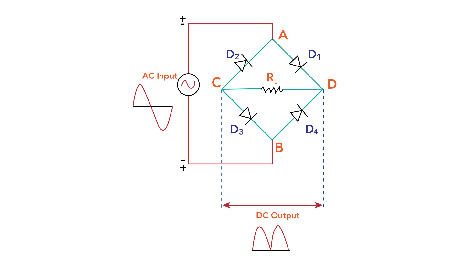
Diodes: Connect the four diodes in a diamond shape, forming the bridge configuration. Label the diodes as D1, D2, D3, and D4 for reference.
Load resistor: Connect the load resistor across the output terminals. This resistor is often used to simulate the load in practical applications.
Filter capacitor: Optionally, if a smoother output is desired, connect a filter capacitor in parallel with the load resistor. The capacitor helps reduce the ripple voltage and provides a more stable DC output.
The AC input voltage can be connected to the transformer primary, and the rectified DC output can be obtained from the output terminals of the bridge rectifier.
Working Principle of a Bridge Rectifier
The working principle of a bridge rectifier is based on the fact that diodes allow current to flow in one direction but block it in the opposite direction. The bridge rectifier’s diodes conduct current alternately during the two halves of the input cycle when an AC voltage is applied to the input.
Positive Half Cycle
The diode linked to the positive terminal of the alternating current (AC) input voltage allows current to flow during the positive half-cycle, whereas the diode attached to the negative terminal blocks current flow. As a result, across the load, a positive half-cycle output is produced.
Negative Half Cycle
The diode attached to the negative terminal of the alternating current (AC) input voltage permits current flow during the negative half-cycle, in contrast to the diode connected to the positive terminal, which inhibits the current flow. A negative half-cycle output is consequently generated across the load.
Overall Output
Combining these positive and negative half-cycle outputs generates a continuous and pulsating DC voltage across the load. It is common practice to connect a filter capacitor in parallel with the load to smooth out pulsations, lower ripple voltage, and create a more stable DC output.
Difference between Full Wave Rectifier and Bridge Rectifier
The primary distinction between the bridge and full wave rectifiers is how they operate and convert AC to DC. The main variations are as follows:
| Key Differences | Full Wave Rectifier | Bridge Rectifier |
| Circuit Configuration | A center-tapped transformer and two diodes are used by the full wave rectifier to convert AC to DC. It requires a transformer with a center tap on the secondary winding. | Contrarily, a center-tapped transformer is not necessary for the bridge rectifier. To convert AC to DC, it uses four diodes set up in a bridge configuration.
. |
| Transformer Requirement | The full wave rectifier requires a center-tapped transformer to provide the necessary input voltage. | A center-tapped transformer is not necessary for the bridge rectifier. It can be used with a standard transformer. |
| Diode Usage | The full wave rectifier uses two diodes at a time, conducting current during alternating halves of the input AC cycle. | The bridge rectifier utilizes four diodes simultaneously, allowing current flow in both positive and negative halves of the input AC cycle. |
| Voltage and Current Ratings | Due to the center-tapped transformer, the full wave rectifier can handle higher voltage and current ratings. | The bridge rectifier can also handle significant voltage and current ratings, making it suitable for various applications. |
| Efficiency | The full wave rectifier is slightly less efficient compared to the bridge rectifier because it uses only two diodes at a time, resulting in higher voltage drops. | The bridge rectifier is more efficient as it uses all four diodes simultaneously, reducing voltage drops and power losses. |
| Size and Cost | The full wave rectifier circuit with a center-tapped transformer tends to be larger and more expensive. | The bridge rectifier circuit is relatively compact and cost-effective due to the absence of a center-tapped transformer. |
Both the full wave rectifier and bridge rectifier serve the purpose of converting AC to DC, but the choice between them depends on the specific requirements of the application, such as voltage and current ratings, efficiency, cost, and available transformer configurations.
Conclusion
The full wave bridge rectifier is a widely used circuit that effectively converts AC voltage into DC voltage. The bridge rectifier circuit is highly efficient and widely used due to its simplicity and ability to convert both positive and negative halves of the AC input waveform into DC. It is capable of delivering higher current and voltage outputs compared to other rectifier configurations.

