Feedback systems use the output signal to change the input signal. These systems take the output signal and compare it with the input reference signal. After comparing, we will get an error signal. This error signal will then control the system output. It can change system gain, frequency response, bandwidth, stability, and distortion.
You can make simple feedback systems that change signals using separate parts like transistors, resistors, and capacitors. You can also use small computers and special chips to make more complicated feedback systems that work with numbers.
Open-loop systems do not care about changes in the circuit or the load. They don’t try to fix problems caused by things like gain, stability, temperature, voltage, or disturbances. However, these gain issues can be solved using feedback mechanisms.
There are multiple electronic circuits where feedback systems are used. Common circuits where feedback signals are used include amplifiers, oscillators, and process control systems.
Two main types of feedback systems are there. Positive and Negative. Positive feedback systems boost the system’s gain and can cause oscillations, which may lead to system instability. Negative feedback systems lower the system’s gain and can improve the system’s performance and accuracy.
Quick Outline:
- Feedback System Block Diagrams
- What is Positive Feedback
- Positive Feedback of an Op-Amp Circuit
- What is a Negative Feedback System
- Negative Feedback of an Op-Amp Circuit
- Classification of Feedback System
- Series-Shunt Configuration
- Shunt-Shunt Configuration
- Series-Series Configuration
- Shunt-Series Configuration
- Conclusion
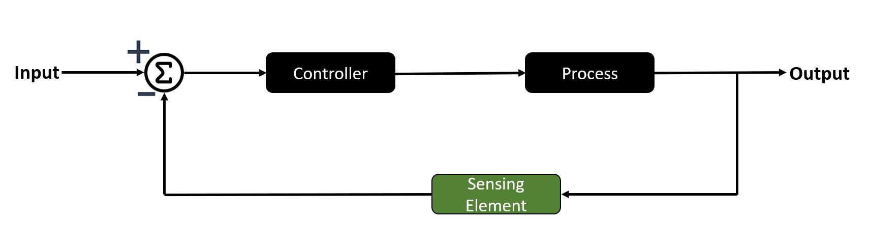
Feedback System Block Diagrams
Feedback systems have four parts: reference input, controller, plant (or process), and sensor. The reference input is the target value or signal that the system should produce. Next, the controller will check the reference input signal and compare it with the feedback signal that we received from the sensor.
This comparison will result in an error signal. This error signal tells the plant what to do. The plant makes the output signal. The sensor watches the output signal and sends it back to the controller.
Feedback Control Systems in Electronics
Feedback systems use the output signal and modify the input according to that output signal. This will overall improve system performance.
You can create feedback systems using electrical, electronic, or digital components. For basic systems, discrete components are sufficient, but for more advanced systems, integrated circuits based on microprocessors are necessary.
The main characteristics of a feedback system in electronics are:
- Using feedback systems, you can easily control the circuit characteristics like gain of system and frequency response.
- These systems can make the circuit characteristics independent of operating conditions. These operating conditions include power supply voltage and temperature.
- Feedback circuits used inside the Op-amps can also reduce the overall signal distortion. These signal distortions are mostly caused by the non-linear properties of other components which are present in a circuit.
- You can control the frequency response, gain, and bandwidth using the feedback in an electronic circuit.
Examples of feedback systems
- Temperature control systems in homes and offices
- Cruise control systems in cars
- Automatic pilot systems in airplanes
- Feedback systems used in medical devices like pacemakers and insulin pumps
- Industrial control systems for machines and processes
What is Positive Feedback
In the positive feedback circuit, the output signal is given back to the input side. This output signal is in phase with the input, meaning that both these signals will be added together. This addition of input and output signal will give you an amplified output. Positive feedback can also sometimes lead to the unstable behavior of the circuit, or will show you the oscillations in output.
You can create different circuits using the positive feedback system. These circuits are mostly oscillators and Schmitt triggers. While using these circuits, make sure to use them cautiously as these can create system instability.
Positive Feedback of an Op-Amp Circuit
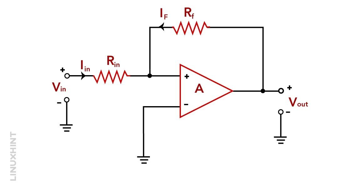
An operational amplifier is an example of a positive feedback system. The op-amp circuit uses the feedback loop to send a value of output to the input side using the feedback resistor.
The feedback resistor present there will connect the op-amp output to the non-inverting terminal of the input side. This way, you can combine the output voltage with the input voltage. The output result you will be getting from the positive feedback op-amp circuit will be higher and amplified.
If the input voltage given to the op-amp is positive, the op-amp circuit will amplify it and the circuit output will become more positive. After that, the feedback network will send some output back to the input side, which will result in making the output voltage even more positive. This process repeats until the op-amp circuit output voltage reaches the saturation level of the op-amp.
In the second case, when the input voltage Vin becomes negative, it will saturate the negative supply rail. This occurs because of the reverse effect of op-amp. So, the positive feedback in this circuit will not act as an amplifier circuit.
The output voltage quickly saturates to the one supply rail or the other one, because the positive feedback loops follow the principle of more result in more and fewer result in less.
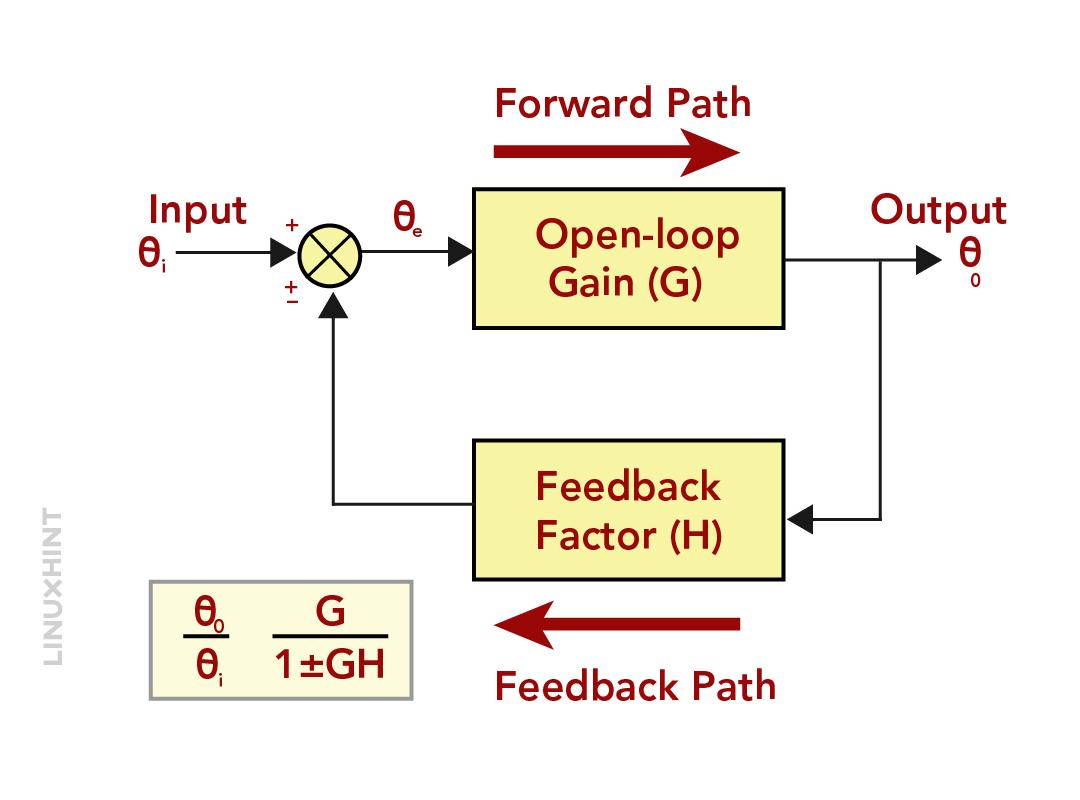
If the loop gain of the system is positive, it means that the system is amplifying the signals. The formula to describe this is:

Where Av is the overall gain, G is the system’s intrinsic gain, and H is the feedback from the output to the input.
When the value of GH becomes 1, the gain of the system will become infinite, and the system starts to self-oscillate. It means that the system will now generate its own continuous output without any need for an input signal. You can use this self-oscillation circuit to make the electronic oscillators that switch very quickly.
Although this behavior is undesirable, it has practical use. Positive feedback can cause hysteresis, which occurs when a device or system maintains a specific state until an input exceeds a given threshold. This characteristic, referred to as bi-stability, is frequent in logic gates and digital switching devices such as multivibrators. It enables these devices to hold a state until a given condition is satisfied, at which point they rapidly flip to a new state.
What is a Negative Feedback System
A negative feedback system uses a part of the output signal and gives it back to the input side. This feedback signal is opposite to the input signal of the system. Negative feedback can affect the system in different ways. It can reduce the gain of the system, and improve the performance of the system and accuracy. It also stabilizes the output of the system and increases its bandwidth.
Negative feedback in an op-amp is implemented by connecting a small portion of the output signal back to the inverting input of the op-amp. This causes the op-amp to amplify the signal, which we get after obtaining the difference between the input and the feedback signal. You can also adjust the feedback of the system by adjusting the value of the feedback resistor. If the feedback applied is more, the amplifier gain will be less. However, more feedback also improves the stability and accuracy of the amplifier.
The negative feedback system compares the set reference input to the output values.
The system subtracts the output from the set point to get the error. This error signal tells the system to adapt itself according to this feedback.
The feedback of the negative system is out-of-phase with the input. This means that the feedback signal is in the opposite direction compared to the input. Due to negative feedback, the system is less responsive to changes. For example, if someone says something bad about you, you feel sad and low. You don’t feel like doing anything.
Negative Feedback of an Op-Amp Circuit
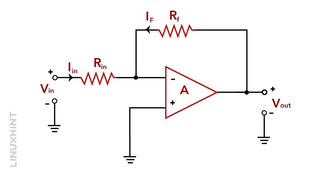
In the amplifier circuit with a negative feedback system, the portion of output (Vout) is applied to the inverting (-) terminal of the input via the feedback resistor Rf.
When positive input voltage in is given to the op-amp, it produces a proportional negative output voltage due to the inverting configuration of the amplifier. A fraction of this output voltage is again given back to the input through the feedback resistor Rf, forming a negative feedback loop.
This will result in a reduction of input voltage by the negative feedback signal. It will also give an even smaller output voltage and so on. After some time, the output will become stable at a value that you can find from the ratio of the feedback resistor to the input side resistor (Rf/Rin).
Similarly, when the negative input voltage Vin is given to the op-amp, the reverse will happen. The output of the op-amps will become positive (inverted). This positive output will be added to the negative input signal. This will help the circuit to work like an amplifier if the output comes within saturation limits.
So we can see that the feedback stabilizes and controls the output voltage because more results in less and less results in more in the negative feedback loops.
The transfer function for the loop with positive system gain will be:

Negative feedback is commonly used in electronic systems to make them stay stable and avoid unwanted fluctuations. It acts like a safety mechanism to prevent these systems from getting out of control when things change.
Another advantage is that negative feedback helps electronic systems to modify system gain with changes in their components and inputs. However, it’s important to use negative feedback carefully because it can change how the electronic system operates.
Classification of Feedback System
So far, we’ve learned about two types of feedback in systems: Positive Feedback and Negative Feedback. However, there are four main ways to classify feedback based on how the output signal is measured and sent back to the input.
These classifications depend on whether we’re amplifying voltage or current, and what we want the output to be.
1. Series-Shunt Configuration: It involves input voltage and output voltage, often referred to as Voltage Controlled Voltage Source (VCVS).
2. Shunt-Shunt Configuration: This one deals with input current and output voltage, known as Current Controlled Voltage Source (CCVS).
3. Series-Series Configuration: In this setup, the input is voltage, and the output is current, often referred to as Voltage Controlled Current Source (VCCS).
4. Shunt-Series Configuration: This configuration uses input current and provides output current and is called Current Controlled Current Source (CCCS).
1. Series-Shunt Configuration:
Series-shunt feedback (Series voltage feedback) works as a voltage-voltage-controlled feedback system. The error voltage that you get from the feedback network is then added to the input voltage in series. The feedback voltage of this configuration is proportional to the system output voltage (Vo). This is because it’s connected in parallel or shunt with it.
In the series-shunt configuration, we get the ratio of both output voltage (Vout) and input voltage (Vin). The series-shunt feedback system is used by both inverting and non-inverting op-amp circuits. This is also called a voltage amplifier. In this configuration, the voltage amplifier’s ideal input resistance (Rin) is very high. On the other hand, the ideal output resistance (Rout) is very low.
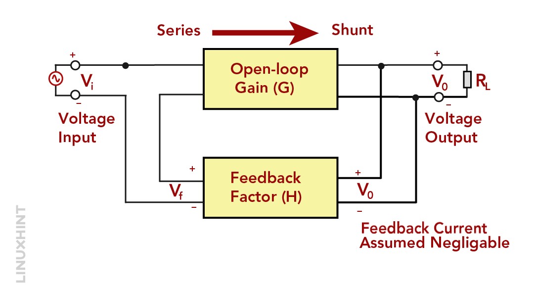
The series-shunt feedback configuration is totally a voltage amplifier because it can take the voltage as input and provide you with a voltage output. You can write the amplification equation as:

The above equation will give you a dimensionless value because it is the ratio between two quantities.
Examples of series-shunt feedback systems are amplifiers and control circuits. Using this series-shunt feedback system, you can control the temperature of the room or the speed of a motor.
An example of a series shunt is a Voltage feedback amplifier, a current feedback amplifier.
2. Shunt-Shunt Configuration:
Shunt-Shunt Feedback Systems (shunt-voltage feedback) is a current-voltage controlled feedback system. In this shunt-shunt feedback configuration, the signal that is given back to the input side is parallel with the input signal. After measuring the output voltage, one thing you should remember is that the current that is subtracted from the input current is the shunt, not the voltage.
We can define the shunt-shunt configuration as the output voltage Vout to the input current Iin. Both the input and output impedance are reduced by the shunt connections at both the input and output terminals, as the output voltage is given back as a current to a current-driven input port.
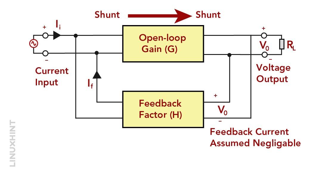
Hence, the system operates most effectively as a transresistance system. In this system, the ideal input resistance (Rin) is extremely low, and the ideal output resistance (Rout) is also very small. As in this configuration, the input is a current signal and the output is a voltage, so the shunt voltage configuration will act as a transresistance voltage amplifier.
The transfer gain is calculated as:

Shunt-shunt feedback systems are not used as frequently as we use the series-shunt feedback systems, but they still have some applications in different electronic circuits.
Shunt-shunt feedback systems are used in regenerative amplifiers, which can amplify weak signals. It is also used in oscillators, which can generate electronic signals at a specific frequency.
An example of a Shunt-shunt configuration is a Regenerative amplifier and oscillator circuits.
3. Series-Series Configuration:
In the series-series feedback system, the feedback element is connected in series with both the input signal and the output signal. This configuration is not that common in use, as this can lead to system instability. However, you can use this configuration in special applications like the design of filters and equalizers.
In a voltage-current controlled feedback or a series-current feedback system, the input and the feedback error signal are in series. The feedback error signal depends on the load current Iout value. This system works by changing the current signal into a voltage signal. This voltage signal is then given back and subtracted from the input of the circuit.
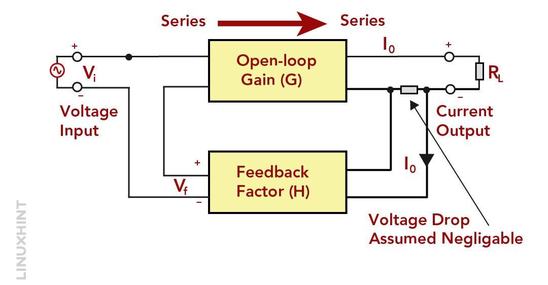
In a series-series connection, the input voltage Vinis related to the output current Iout. The output current Input is converted into a voltage signal and given back to the input side in series. This will make the input and output impedance of the system higher. Using this configuration, you can easily design a transconductance amplifier. This amplifier has a very large ideal input resistance Rinand a very large ideal output resistance Rout.
A transconductance-type amplifier has voltage input and current output. This is how the series-series feedback configuration works. The feedback circuit converts the output current Iout into a voltage and gives it back to the input side in series.
The transfer gain of this system is:

An example of a Series-series configuration is a Filter and equalizer.
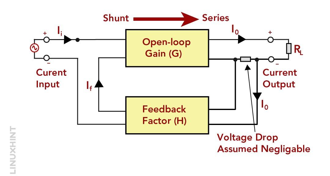
4. Shunt-Series Configuration:
A current-current controlled feedback system is also known as a shunt-series feedback or a shunt current feedback system. In this system, the output current Io flows in the load and determines the feedback signal. The feedback signal of this shunt-series configuration is parallel or shunt with the input.
The shunt-series feedback system contains two signals, which are a current input signal and a current output signal. The configuration of this feedback system is based on the ratio between the output current Iout and the input current Iin. The feedback signal depends on the output current Io that goes through the load.
This feedback signal is added to the input signal in parallel or shunt. This will combine the current, but not the voltages.
As the voltage input is needed for the voltage output, the system’s voltage gain is not affected by the parallel shunt feedback connection. The output resistance Rout is increased by the output series connection. While the input resistance Rin is decreased by the parallel or shunt connection at the input side.
A current amplifier is a system that has a current input signal and a current output signal. This is how the shunt-series feedback configuration works. The feedback signal is in proportion with the output current Io. It is added to the input signal in parallel or shunt.
The transfer gain equation of the system can be given as:

As it is the ratio between two similar quantities of amperes to amperes, it has no unit.
An example of a shunt-series configuration is the Schmitt trigger and oscillator circuits.
Conclusion
In a feedback system, the output signal is sampled and looped back to the input side. This feedback system will generate an error signal that monitors the system’s behavior. Feedback signals can be of both nature; they can be either a voltage signal or it can be a current signal.
Feedback signals can be positive as well as negative. If the feedback of the system gives you a negative loop gain, the feedback will be negative or degenerative. While, if the loop gain is positive, it will be called positive feedback or regenerative feedback system. Positive feedback can also increase the system gain, which sometimes can lead to system instability.
We have also seen several types of feedback systems based on current and voltage output. There are four types of feedback configuration: series-voltage, shunt-voltage, series-current and shunt-current feedback. Naming conventions for these feedbacks are derived from the way they connect the input and output of the system. It can be either in parallel (shunt) or in series.