The combination of different electrical systems that collect information is known as electronic systems. There are many ways to represent a system such as designing a mathematical model of the system, describing the system in text format, showing the graphical representation, and many other ways.
Electronic Systems and Electronic Control Systems
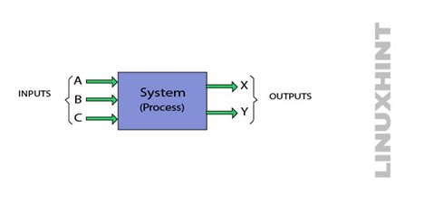
The electronic system is represented by the combination of blocks. Each block in the system may represent a single component or may consist of several components. The below-given figure below shows the simplest representation of an electronic system. It consists of three inputs that go to a process and result in two outputs:
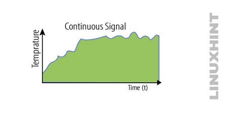
The electronic systems work on two types of signals such as continuous time signals and discreet signals. The continuous-time signal is defined as the signal that continues with time below is the representation of the continuous signal:
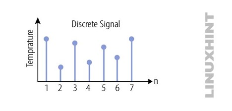
The discrete signal is defined as the signal that is not continuous with time, but sometimes shows pattern and sequence series, below represent the discrete signal:
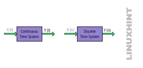
The figure shows the block diagram of both continuous and discrete signals:
There are different types of systems in electronics:
Series Connected System
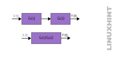
This type of system is also known as a cascaded system. In this type of system, the output y(t) is obtained by multiplying the system G1(s) and G2(s). The below figure represents the series connected system. The mathematical representation of the series connected system is given as:
In the above equation, G represents the transfer function which is defined as the ratio of output and input.
Parallel Connected System
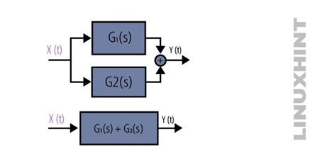
The type of system in which each individual receives the same input, and the result output is the sum of all the systems. The below figure shows the prototype of the parallel connected system. The mathematical representation of the parallel connected system is given as
Feedback Connected System
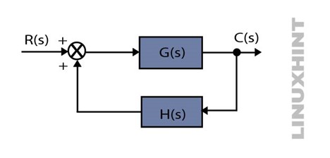
This is the most important type of system in which the output of the system is feedback, and it is either added or subtracted from the input. The figure below represents the feedback system. The formula to represent the transfer function is given as:
Conclusion
Control systems are primarily designed to achieve the desired output by altering the input methods. There are many ways to represent a system such as designing a mathematical model of the system, describing the system in text format, showing the graphical representation, and many other ways. The analysis of any electronic system is based on cause-and-effect analysis.

