Capacitors in electrical circuits are used to regulate the flow of voltage and current in a circuit by absorbing any transients or releasing the extra energy by discharging to compensate for any losses. The characteristics of a capacitor vary based on its composition and structure, and due to this dependency on the characteristics. Electrolytic capacitors are one of the types of capacitors that have an electrolyte as one of its plates which reduces its size to a greater extent.
Outline:
What is Electrolytic Capacitor
Construction of Electrolytic Capacitors
Working of Electrolytic Capacitors
Type of Electrolytic Capacitors
Characteristics comparison of Electrolytic Capacitors
Conclusion
What is Electrolytic Capacitor
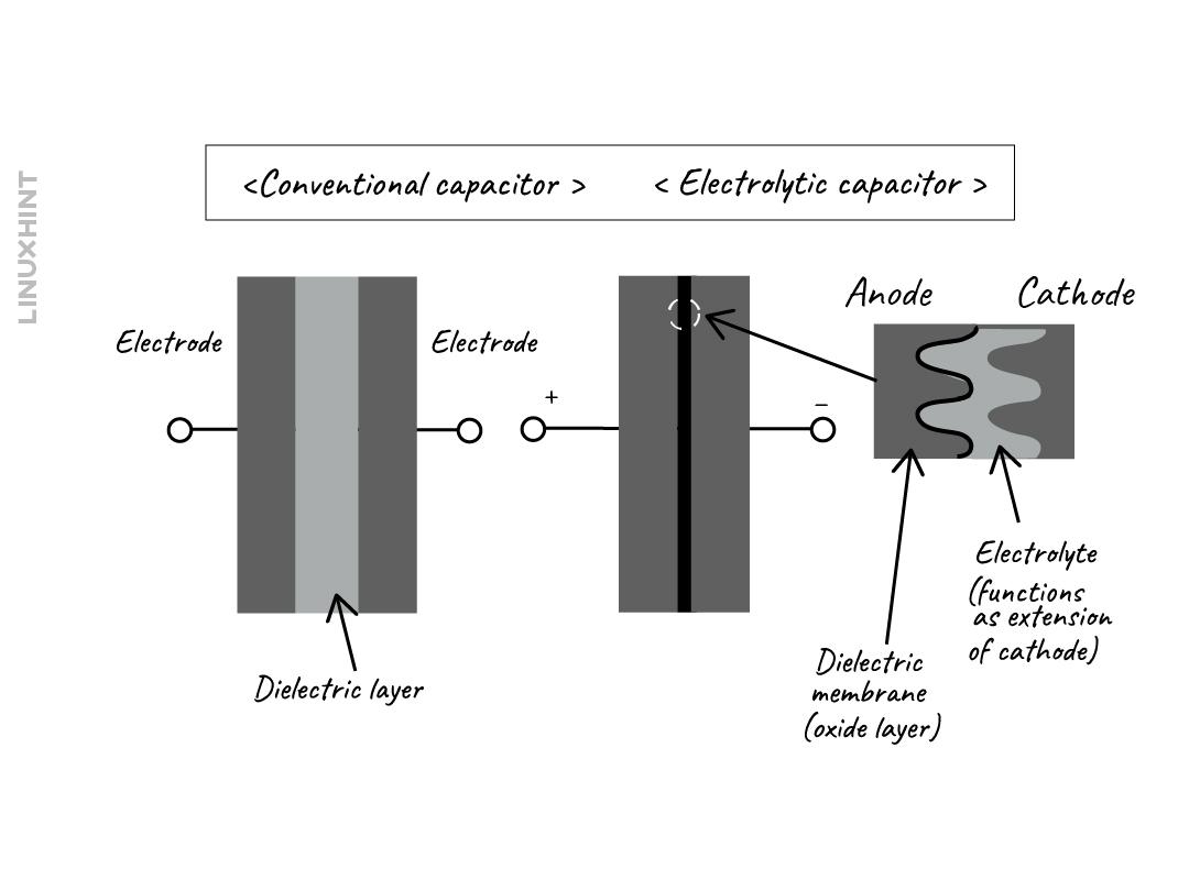
An electrolytic capacitor is a polarized capacitor that can only work with a single polarity, that is it can work well in DC circuits. Moreover, these capacitors have one metal electrode and the other one is a semi-fluid material that acts as a cathode. The electrolyte is a material that has a high concentration of ions, due to this chemical composition these capacitors have higher capacitance as compared to the other types of capacitors.
Construction of Electrolytic Capacitors
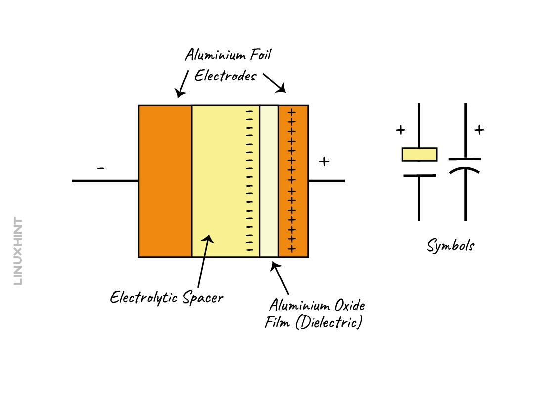
The electrolytic capacitors have two thin foils made up of aluminum, one of which has an oxide layer sprayed on it that acts as a dielectric. Whereas the other foil is dipped in an electrolyte which acts as a cathode and due to this construction, the surface area of the cathode plate is increased, thus resulting in increased capacitance.
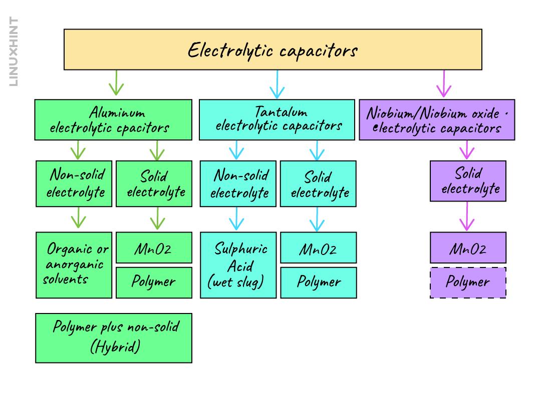
Now based on the materials of the electrolyte, the capacitor is divided into two types, one is wet type and the other is dry type. Moreover, the electrolyte materials are the oxides of niobium, aluminum, and tantalum and the types of wet electrolytic capacitors are named based on these oxides. The solid or dry electrolytes used are magnesium dioxide and organic polymer conductive material.
The oxides are formed automatically in the air when a constant current passes through the metal electrode and this builds up the dielectric layer that is the oxide layer. So, when the formation voltage of the aluminum foils of the electrolytic capacitors increases to a certain limit the growth of the oxide layer is to be halted. For wet electrolytic aluminum capacitors, the formation voltage is approximately 500 Volts whereas for wet tantalum capacitors, it is around 300 Volts. The build-up of the oxide layer is commonly named as formation or anodic oxidation, and the formation voltage continues to rise until it supersedes the rated voltage.
Working of Electrolytic Capacitors
When a DC supply is connected with the electrolytic capacitor, the formation of the layer of dielectric starts, and the current starts to flow from the electrolyte. The voltage difference between the anode and the cathode creates an electric field in the electrolyte forcing the ions to migrate. The positive ions in the electrolyte are attracted by the cathode and the negatively charged ions are attracted by the anode. These ions form bonds with the electrodes which result in the formation of an electrostatic double layer.
This double layer is created between the electrolyte and electrode, and from this region the charge transition takes place. So, when the capacitor is fully charged, all the ions are in the formation layer and when the capacitor begins to discharge the attracted ions move back into the electrolyte.
Type of Electrolytic Capacitors
The electrolytic capacitors are primarily distinguished based on the dielectric and the anode material composition. The classification of electrolytic capacitors is given below in the image:
Aluminum Electrolytic Capacitors
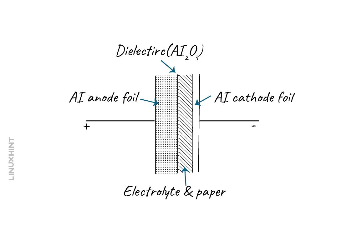
The aluminum electrolytic capacitors come with two conductive material layers that are separated by an oxide layer which serves the purpose of dielectric. One electrode which is made up of aluminum foil has a large surface area that acts as an anode and a layer of aluminum oxide is built up on it which will be used as a dielectric. Moreover, the other electrode of the capacitor is a liquid that has conductive ions and is often referred to as an electrolyte. The other aluminum foil is in contact with the electrolyte which can be named the cathode foil, and it provides a large surface area to current to pass through the electrolyte.
The dielectric of the aluminum electrolytic capacitor is formed as a result of oxidation of the aluminum oxide layer. The thickness is proportional to the forming voltage that has a rate of 1.2 nm/V and the maximum attainable thickness of the layer is around 1µm even in the case of high voltages. When the forming process starts the pits of foils encrust which are in proportion to the forming voltage. So, it is necessary to take into account the final operating voltage during the forming process.
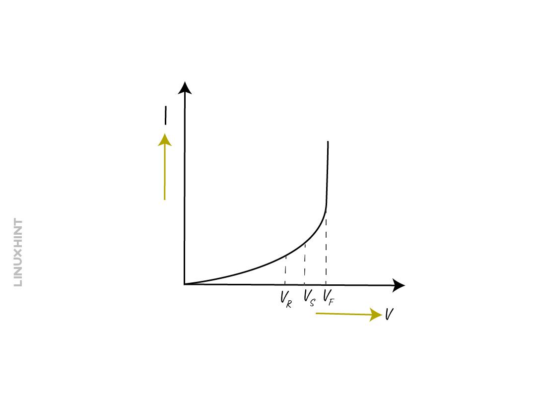
Due to the formation of this oxide layer, the capacitor exhibits non-linear characteristics and as a result, the DC current tends to increase steadily, below is the characteristic curve of the aluminum electrolytic capacitor.
Here VF is the formation voltage, VS is the surge voltage and VR is the rated voltage so when the formation voltage increases the process of formation of oxide layers starts. To keep the rated voltage on the safe side it is defined as part of a quasi-linear point of the curve. The range of the surge voltage lies between the rated voltage and the formation voltage. The operating reliability of the capacitor is affected by the over anodization of the oxide layer, that is the increase in its thickness. So, the higher the anodization the higher will be the reliability of the capacitor.
Failure Modes of Aluminum Electrolytic Capacitors
The capacitors can malfunction despite being reliable, as there are a number of factors that affect the functioning of a capacitor. So here are some modes of failures of Aluminum electrolytic capacitors along with their causes:
| Modes of Failure | Brief Description and Causes |
|---|---|
| Electrolyte Leakage | The leakage of electrolytes happens due to various reasons which include an increase in the internal temperatures, over-voltage, and deterioration of the inner shell of the capacitor. |
| Open Vent | The open vent in the electrolytic capacitors is a safety feature that releases excessive internal pressure and heat. If this vent fails to open, then this could lead to failure of the capacitor and this failure is caused by reverse voltage |
| Open circuit | The electrolytic capacitor behaves as an open circuit either due to high mechanical stress or due to the evaporation of electrolyte. The evaporation can occur when the capacitor is subjected to overvoltage, or the internal pressure and heat is increased. |
| Short Circuit | The electrolytic capacitor behaves as a short circuit due to an increase in the reverse voltage, ripple currents, dielectric breakdown, and bad foil edges. |
| Increase in Leakage Current | The aluminum electrolytic capacitors can bear the small leakage current but with the passage of time due to the deoxidation of the oxide layer. Moreover, corrosion is also a major factor in increasing the leakage current in aluminum electrolytic capacitors |
Self-healing in Aluminum Electrolytic Capacitors
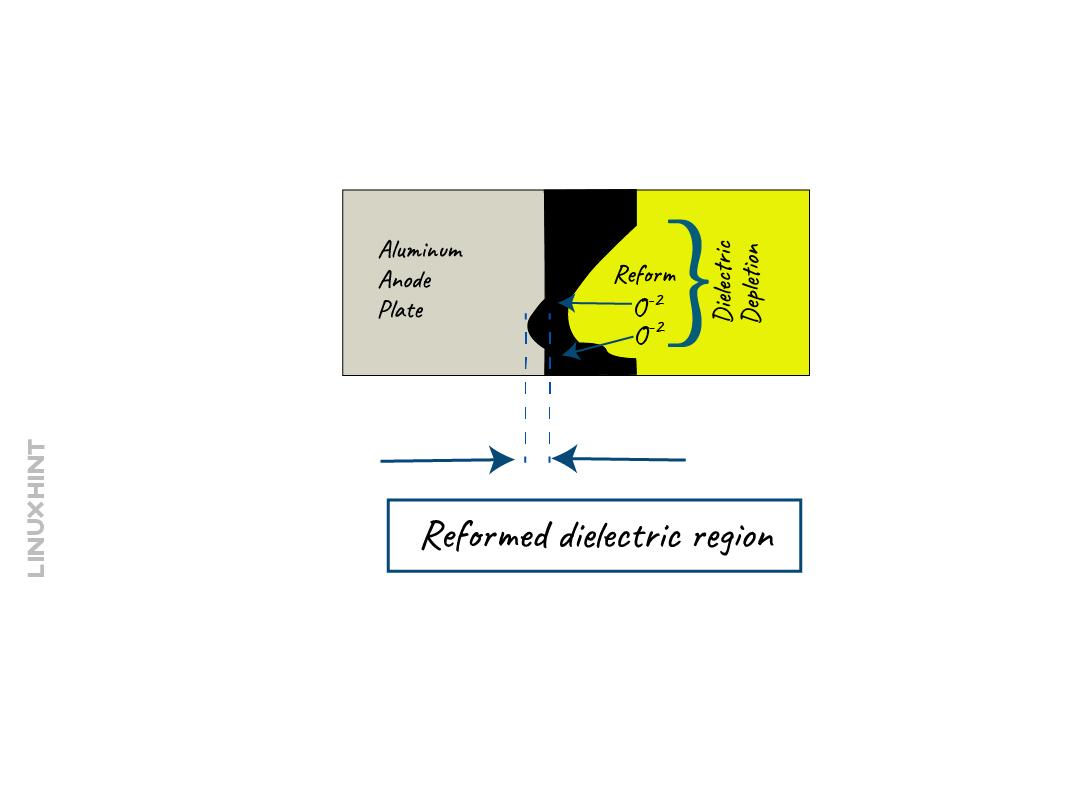
When the electrolyte reacts with the oxide layer of the aluminum electrolytic capacitor it begins to deplete, and this mostly happens when the capacitor is not connected to the power supply for a longer span of time. Due to this deformation of the oxide layer, the voltage starts to decrease but the leakage current remains the same, however, the leakage current contributes to reforming the oxide layer.
In the reformation process, the oxygen atom from the water is extracted and bonded with the aluminum, which in turn creates the aluminum oxide. Moreover, the hydrogen gas left behind is released through the open vent of the capacitor. So, this process of reformation of the oxide layer is referred to as the self-healing which prevents the short circuit of a capacitor. It is to be noted that leaving the capacitor unpowered for a longer time can result in the depletion of the oxide layer and the reformation process can only occur when it is connected to the power supply.
Tantalum Electrolytic Capacitors
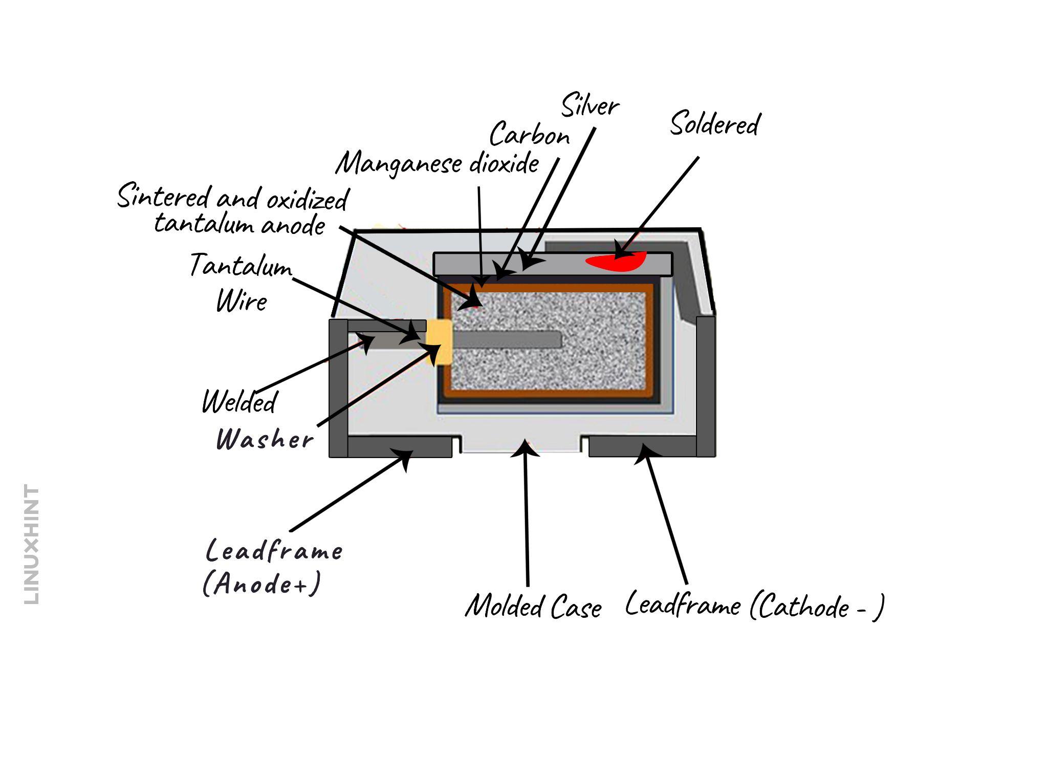
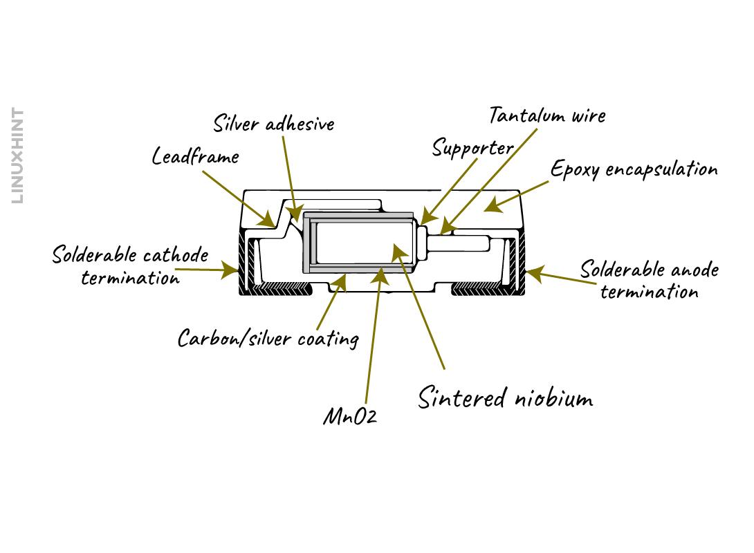
These capacitors have solid electrolytes having tantalum oxide as a dielectric and create the shape of a sintered pellet. The material for the anode of this capacitor that is mainly used is tantalum powder and for the cathode, it is magnesium oxide. The dielectric has a maximum thickness of 1.7 nm/V whereas the breakdown voltage is approximately 625 V/um.
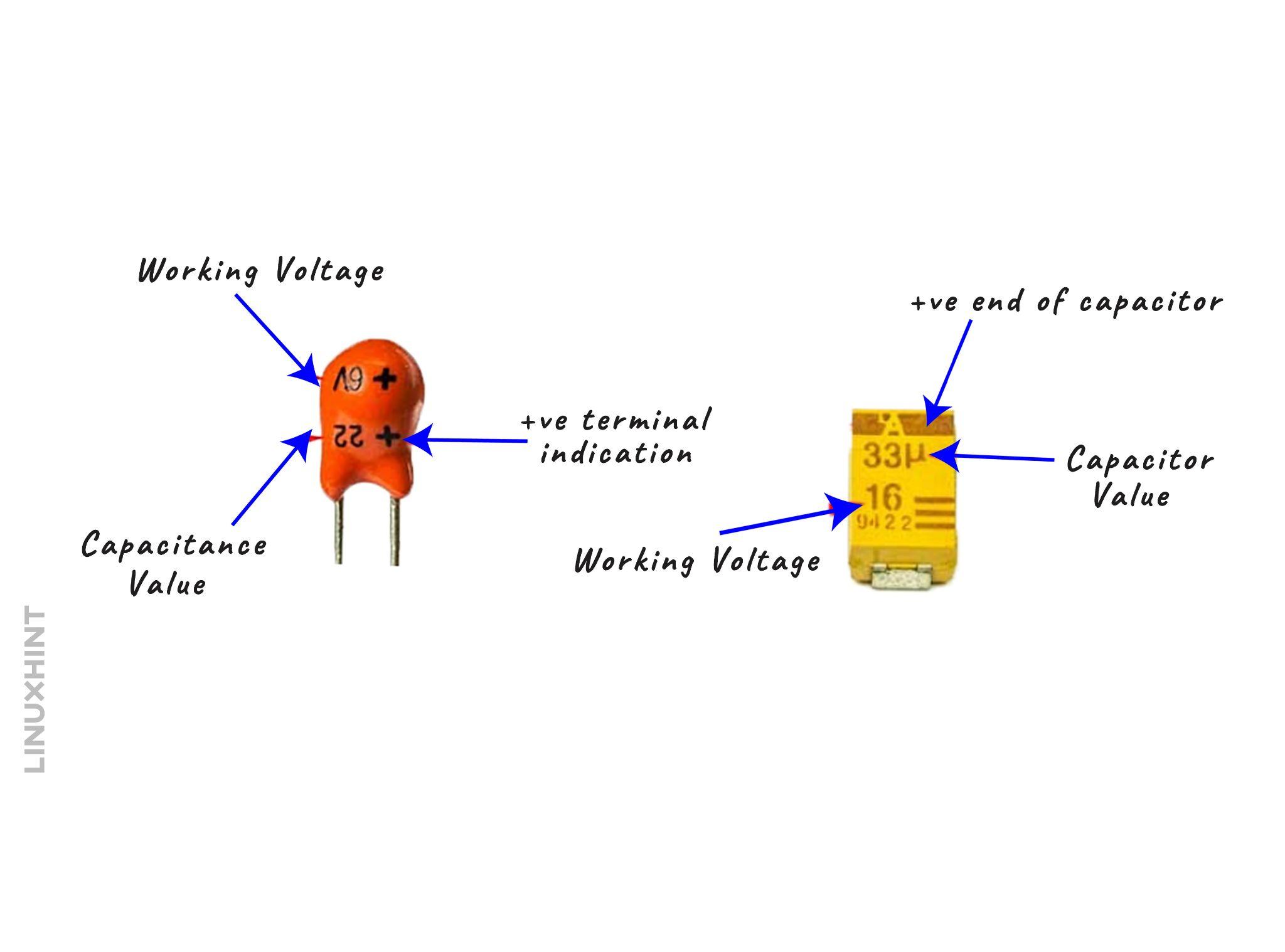
When compared with the aluminum electrolytic capacitors these have lower leakage current and higher capacitance. These capacitors are highly polarized and are sensitive to the reverse voltages as even a minor reverse voltage can lead to their breakdown. This is because the dielectric breaks down due to the reverse voltage thus creating a short-circuit. The tantalum electrolytic capacitors are further divided into two types: lead tantalum and SMD tantalum Capacitors:
These capacitors are suitable for applications where there is a low leakage current, and higher stability, and reliability are required. Here is a table that shows some features of tantalum electrolytic capacitors:
| Technology | Tantalum |
|---|---|
| Anode | Tantalum |
| Electrode | MnO2 |
| Basic reliability | 1%/1000 hrs @ 85 °C |
| Capacitor Range | 0,1-1000 µF |
| Capacitor Tolerance | 10 % to 20% |
| Rated Voltage | 2.5 – 50 |
| ESR (D case typical) | 35-100 mΩ |
| Dissipation Factor | 4-16% |
| Leakage Current | 0.01 CV |
| Derating in low imp. Circuits | 50% |
| Temperature Range | -55 /+125°C |
Failure Modes of Tantalum Capacitors
Despite having high reliability and stability, there are some factors that can cause the tantalum capacitors to break and here is a table that briefly explains the failure mode for these electrolytic capacitors:
| Modes of Failure | Description and causes |
|---|---|
| High Equivalent Series Resistance | The ESR is a combination of resistance losses that occur due to various factors like resistance in the components and contacts or opposing forces in the dielectric. The tantalum capacitors are designed to work at low equivalent resistances. However, due to the mechanical and thermal impact on the capacitors, the stress is increased which results in high ESR thus causing the failure of the capacitor. |
| Low Capacitance | Usually, the capacitance of tantalum electrolytic capacitors does not change while working in normal conditions. However, if there is a short somewhere in a circuit or the positive leg of the capacitor is damaged then the capacitance might drop. |
| High Leakage Current | As previously mentioned, tantalum Capacitors are highly sensitive to reverse voltage. Due to the increase in the leakage current a reverse voltage is induced which causes the break-down of the capacitor due to opposite polarity. |
Self-healing in tantalum Electrolytic Capacitors
In tantalum electrolytic capacitors, the behavior of the magnesium dioxide anode makes it a self-healing capacitor. During the break-down of the dielectric, the magnesium dioxide gets oxidized due to thermal conditions and the chemical process will result in oxygen and magnesium trioxide:
Due to the increase in the heat, the above reaction takes place, and the oxygen gets absorbed by either the magnesium diode or tantalum oxide but not with the tantalum pentoxide. Magnesium trioxide also has a high resistance which makes it a good insulator.
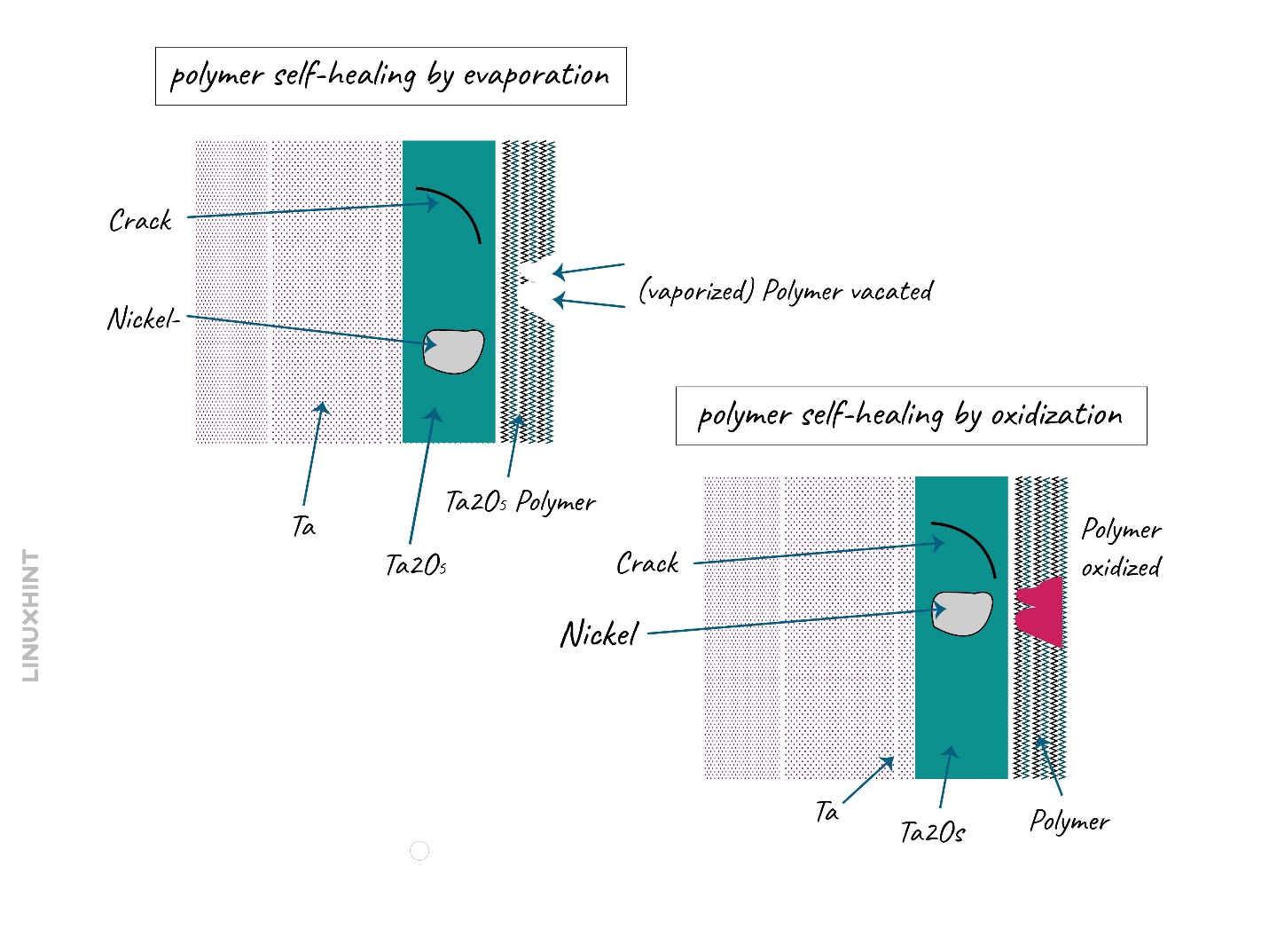
If there is a polymer electrode in the capacitor, then the self-healing process is different from that of magnesium dioxide. Due to having a polymer, oxygen is no longer present in it which reduces ignition energy to a considerable extent. In this case, the area where the dielectric breakdown occurred gets isolated from the other part of the capacitor, either through evaporation or peeling off. Due to this phenomenon, the current flow from the failure area is blocked, thus preventing the capacitor from short circuit. The polymer self-healing is not found to be as effective as compared to the magnesium dioxide self-healing process.
Niobium Electrolytic Capacitors
Niobium Electrolytic Capacitors have the same shape as those of tantalum electrolytic capacitors and also have a lot in common when it comes to their characteristics. This is because niobium is a sister metal to the tantalum metal but there are some downsides of this capacitor as well. The niobium Electrolytic capacitor has niobium pentoxide as a dielectric which has twice the dielectric constant than the tantalum, but the break-down strength gets reduced to half.
The niobium pentoxide is sensitive to higher temperatures and highly reliable between a temperature range of 85 degrees to 105 degrees. This increase in reliability at higher temperatures makes it suitable for industrial applications. Due to the higher dielectric constant, the thickness for dielectric needed is high to reach the same voltage level as that of tantalum. This undoubtedly increases the reliability but there is a limitation for the thickness of the dielectric. However, the rated voltage for niobium is lower than the tantalum capacitors, here is a table that shows the properties of niobium and niobium oxide:
| Parameters | Units | End Value | Niobium | Niobium Oxide |
|---|---|---|---|---|
| Powder | Nb metal | nb0 | ||
| Hardness | Medium | High | ||
| Ore Content | ore/power cost | 3% | 3% | |
| Non-capacitor usage | Availability | 90% | 90% | |
| Density | [g/gcc] | Weight, drop test, CV | 8.6 | 7.3 |
| Ignition Energy | [mJ] | Resistance to burn | 2 | 600 |
| Burning rate | [mm/s] | Burning speed | 8 | 1.5 |
| Specific Heat | [j/mol/K] | Load resistance | 25 | 40 |
| Dielectric | CV | Nb2O5 | Nb2O5 | |
| Thickness | 10-9m/V | CV | 2.5 | 2.5 |
| Dielectric Constant | 41 | 41 |
The one big limitation of the niobium based electrolytic capacitors is that they have lower rated voltage and lower capacitance times voltage (CV). The niobium-based capacitor shows higher dependency on the temperature, yet they are more safe and align with the equivalent series resistance standards. Here are the features for the niobium electrolytic capacitors:
| Technology | Niobium Oxide | Niobium |
|---|---|---|
| Anode | NbO | Nb |
| Electrode | MnO2 | MnO2 |
| Basic reliability | 1%/1000 hrs @ 85°C | 1%/1000 hrs @ 85 °C |
| Capacitor Range | 10-100 µF | 10-100 µF |
| Capacitor Tolerance | 20% (10%) | 20% (10%) |
| Rated Voltage | 4-10 | 4-20 |
| ESR (D case typical) | 100 mΩ | 100 mΩ |
| Dissipation Factor | 6-14% | 4-16% |
| Leakage Current | 0.02CV | 0.01-0.04 CV |
| Derating in low imp. Circuits | 20% | 50% |
| Temperature Range | -55/105°C (+125°C dev) | -55 /+125°C |
Self-healing in Niobium Electrolytic Capacitors
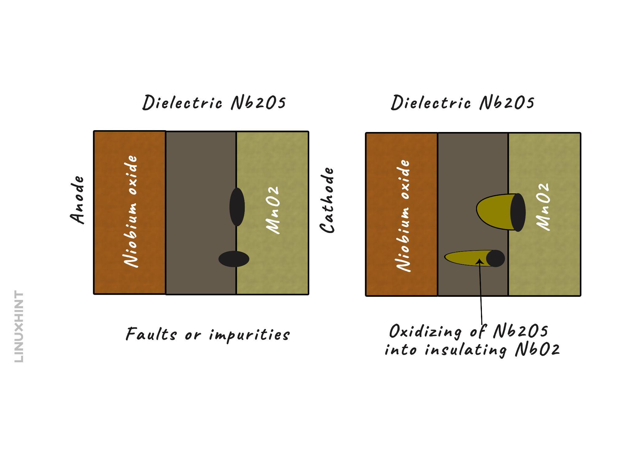
In niobium electrolytic capacitors, the cathode is usually of magnesium oxide and the anode is of niobium oxide. Unlike tantalum, niobium oxide is rich in oxygen content due to which it has high ignition energy however it has a low risk of combustion. The self-healing process of this niobium electrolytic capacitor is quite different and safer from the others thus making it much better than the other electrolytic capacitors. When the dielectric breaks down a niobium dioxide is formed between the dielectric which is niobium pentoxide and the anode which is niobium oxide. Thus, this prevents the capacitor from short-circuit due to the breakdown of the dielectric and the resistance still remains high.
Characteristics comparison of Electrolytic Capacitors
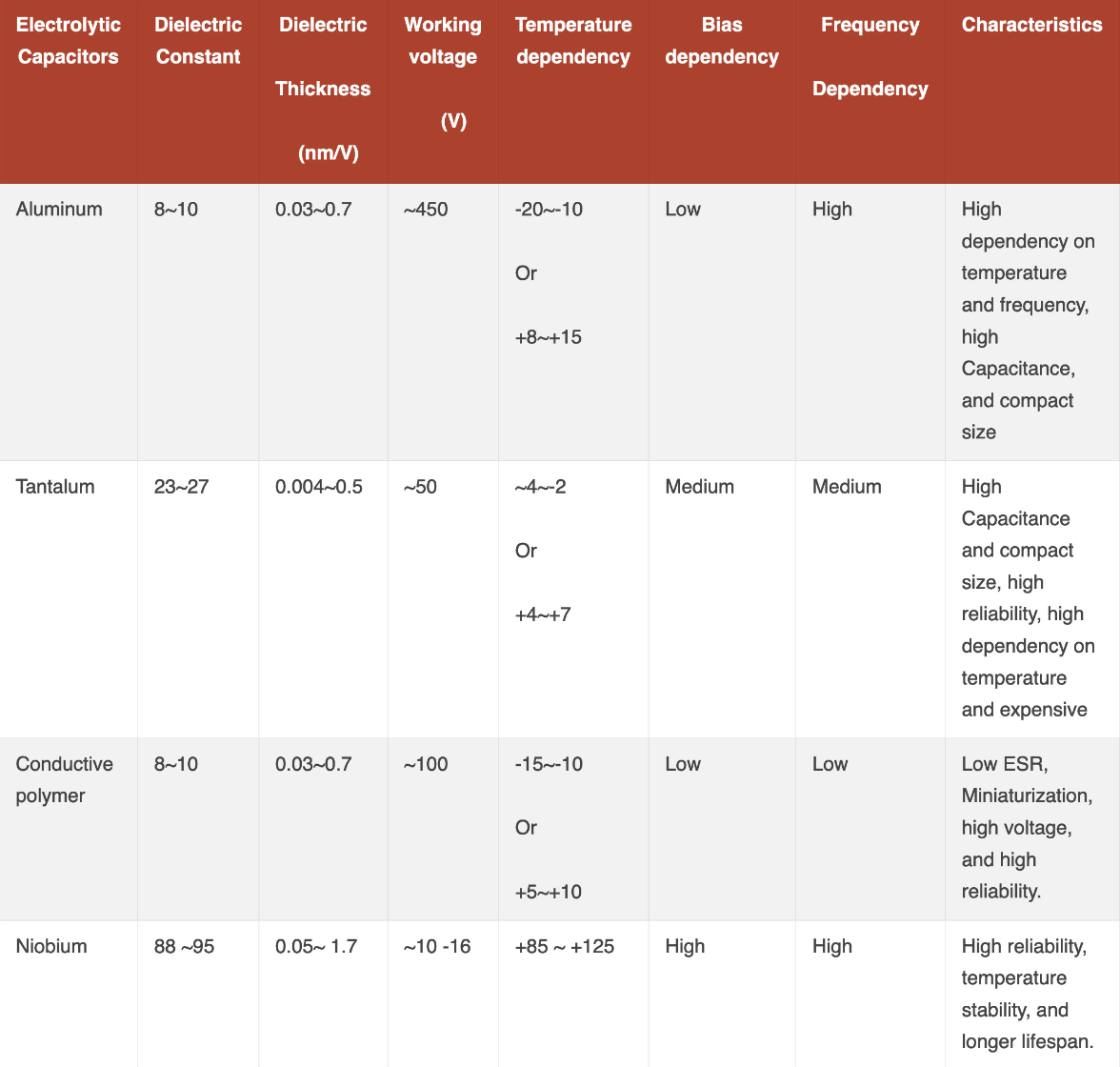
All three types of electrolytic capacitors have different characteristics because their composition is different from one another, so here is a table that displays the characteristics of the three:
Conclusion
The electrolytic capacitors have one electrode as an electrolyte, which gives them higher capacitance as the surface area of the electrode is increased. Moreover, the dielectric is an oxide layer that is formed on the anode electrode when the capacitor is connected to the supply. The electrolytic capacitors are polarized, which means they can break down in case of reverse polarity. Moreover, they have a self-healing feature that prevents the capacitors from malfunctioning.

