The process of data comparison is essential in digital systems when doing arithmetic or logical processes. This comparative analysis assesses and compares the magnitude of two numbers, determining if numbers are greater, lesser, or equal to one another. The digital comparator is extensively utilized in combination systems and is specifically engineered to assess the relative magnitudes of binary integers. This article describes the two types of digital comparators in detail.
Digital Comparators
A digital comparator is a fundamental electronic device that compares two numbers and assesses their magnitudes concerning one another:
A form of combinational circuit called a magnitude digital comparator is used to compare two binary or digital values, A and B, and determine their relative magnitudes. The purpose of this circuit is to ascertain if one number is equal to, less than, or higher than the other digital number.
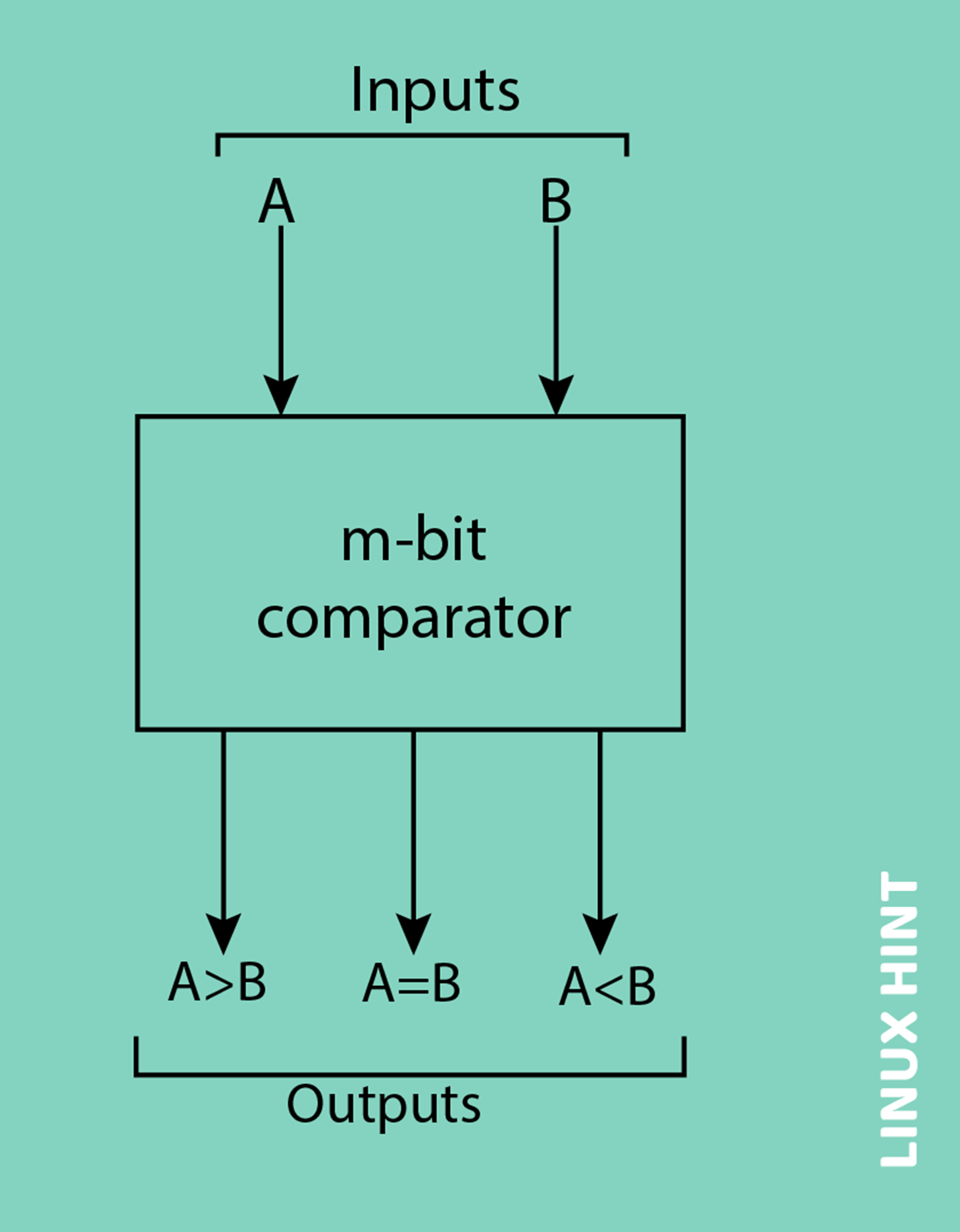
The outcome of the comparison is shown by the use of three binary variables, representing A>B, A<B, and A=B. The above diagram illustrates the block diagram of an n-bit comparator, which is designed to compare two numbers of n-bit length and determine their relative relationship.
The comparators can compare numbers of varying bit lengths, such as 2-bit, 4-bit, and 8-bit, based on the specific requirements of the application.
Notable examples of these ICs comprise the IC 7485, which functions as a 4-bit comparator, the IC 4585, which serves as a 4-bit comparator within the CMOS family, and the IC 74AS885, which operates as an 8-bit comparator.
Classifications
Digital comparators have two main types:
Identity Comparators
Identity comparators have only one output, which can be either high or low. In case both inputs are equal or A=B=1, the output goes high. In case inputs are not equal or A ≠B, the output goes low.
Magnitude Comparators
Identity comparators have three outputs which are based on equal inputs, one greater than the other or one less than the others. High or low. Therefore, the first output goes high if A=B and others remain low. Similarly, in the case of A>B, the second output goes high while the rest is low, and finally, if A<B, the third output goes high.
Single-bit Magnitude Comparator
To compare two bits, precisely two numbers with one bit each, a single-bit comparator is used. The system comprises two input ports designed to accommodate two single-bit numerical values, as well as three output ports that provide outputs indicating whether the values are less than, equal to, or greater than each other.
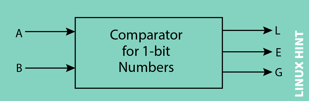
The diagram above depicts the block diagram of a magnitude comparator that operates on a single bit. The comparator under consideration compares two binary bits and generates one of three possible outputs: L (indicating that bit A is less than bit B), E (indicating that bit A is equal to bit B), and G (indicating that bit A is greater than bit B).
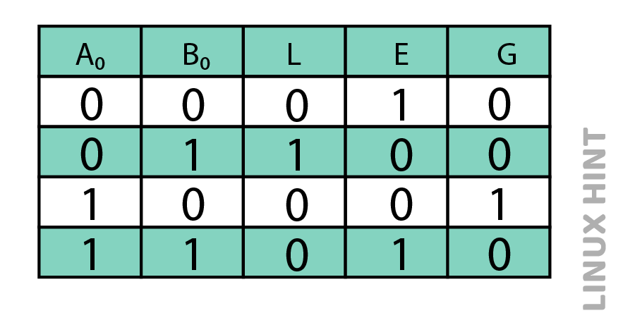
The truth table illustrating the logical operations performed by a single-bit comparator is presented below. In the scenario where A0 B0 results in the binary sequence 00 & 11, it can be observed that both inputs are identical. Consequently, the output A=B will be in a high state. When the product of A0 and B0 equals 01, it can be concluded that B is greater than A, hence resulting in the activation of AB.
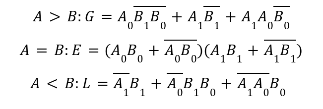
The logical expressions for each output can be stated using the truth table:

The implementation of a logic circuit can be achieved by the utilization of Boolean expressions. This involves the incorporation of one NOT gate, one Ex-NOR gate, and two AND gates as depicted in the picture below. The AND gates are commonly used in determining the relationship between two binary digits, specifically if one digit is bigger than or less than another. On the other hand, Ex-NOR gates are utilized to ascertain the equality or inequality of two binary integers.
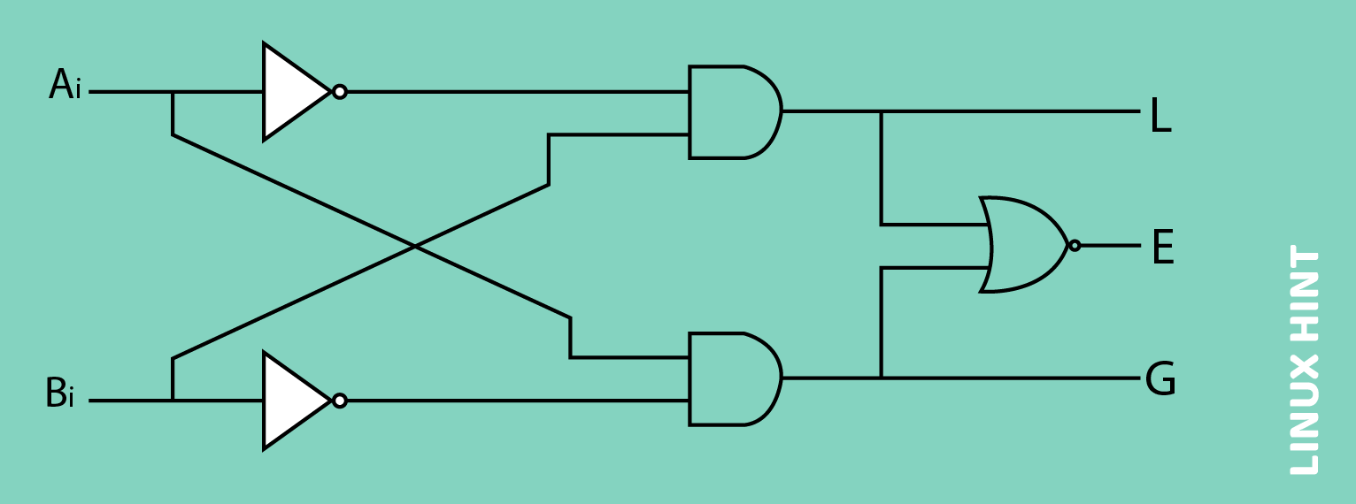
The above diagram shows the configuration of two AND gates. The first AND gate receives inputs A0 and the complement of B0, denoted as (B0) ̅. The second AND gate, on the other hand, receives inputs the complement of A0, denoted as (A0) ̅, and B0. Therefore, the output of an AND gate is 1 when A0 is greater than B0 (specifically, when A0 equals 1 and B0 equals 0), and it is 0 when A0 is less than B0 (specifically, when A0 equals 0 and B0 equals 1).
The output of an AND gate is determined by the condition A0 < B0, where A0 represents the value of A at index 0 and B0 represents the value of B at index 0. Specifically, the output is 1 when A0 is equal to 0 and B0 is equal to 1. Conversely, the output is 0 when A0 is equal to 1 and B0 is equal to 0.
The Ex-NOR gate is equipped with inputs A0 and B0. Consequently, the output of the Ex-NOR gate will assume a value of 1 when A0 is equal to B0, while it will take on a value of 0 when A0 is not equal to B0.
2-bit Magnitude Comparator
This comparator establishes the relationship between two binary values, each of which consists of two bits, namely whether one number is equal to, greater than, or less than the other. The block diagram of a two-bit comparator with four inputs and three outputs is shown in the diagram below.
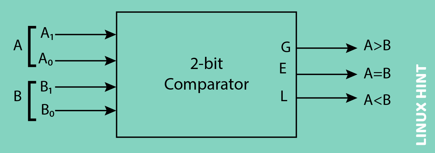
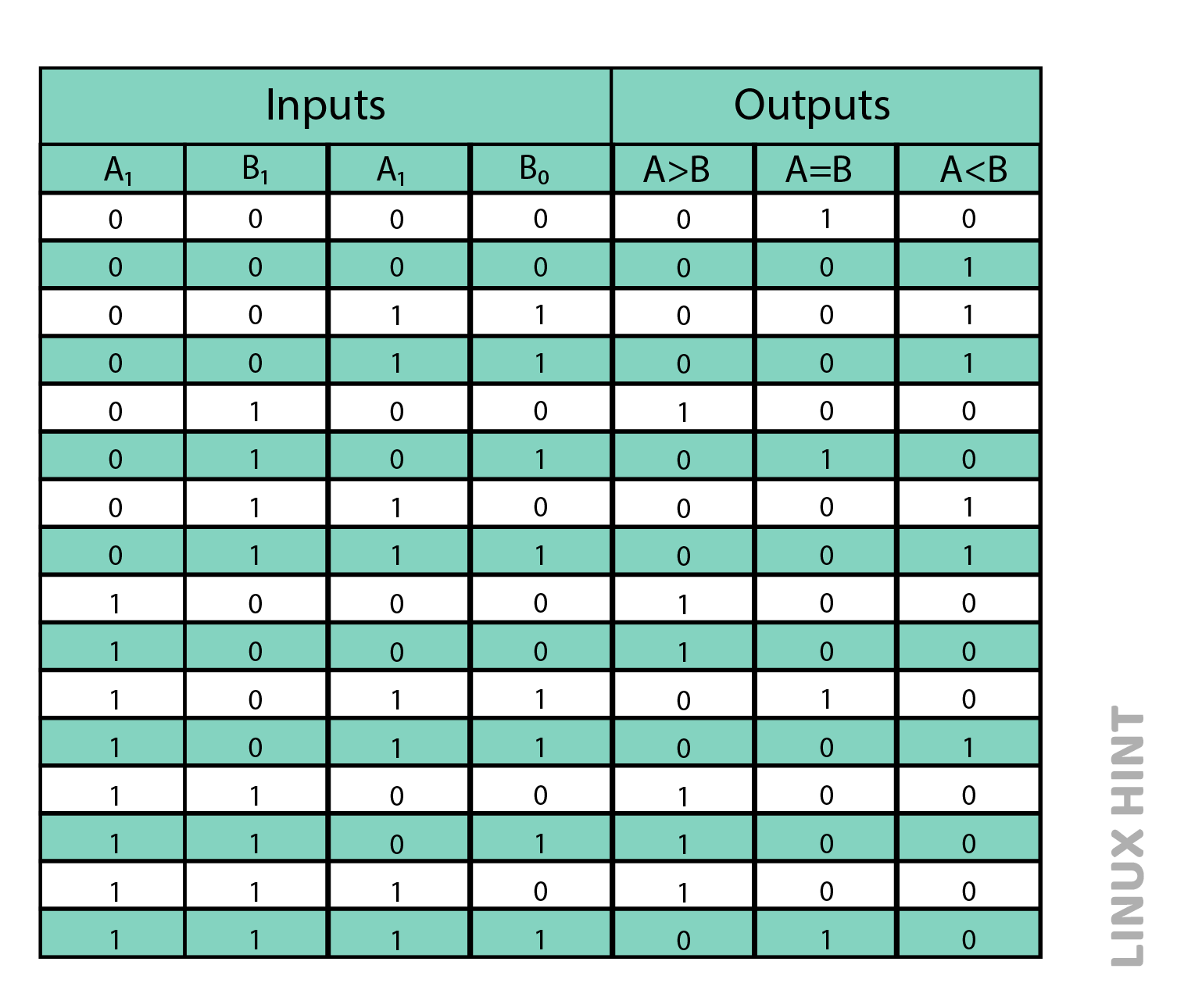
The initial number denoted as A, is represented as A = A1A0, whereas the subsequent number is denoted as B = B1B0. The comparator generates three outputs: G (where G equals 1 if A is more than B), E (where E equals 1 if A is equal to B), and L (where L equals 1 if A is less than B). The truth table presented below shows the different input and output states of this comparator.
Based on the Boolean equation found above for each output, the logic diagram can be implemented using four NOT gates, seven AND gates, two OR gates, and two Ex-NOR gates.
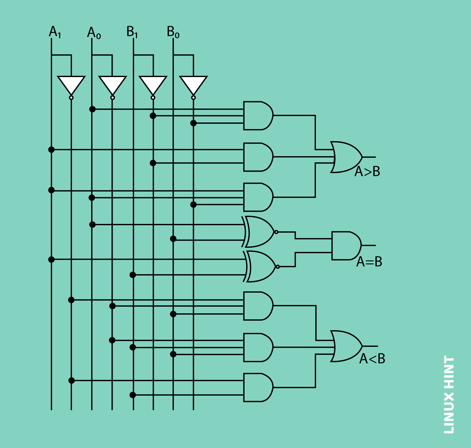
The graphic presented below depicts the logical representation of a 2-bit comparator, using fundamental logic gates. The construction of this comparator can also be achieved through the cascade of two 1-bit comparators.
4-bit Magnitude Comparator
Four-bit comparators do a comparison between two four-bit words. The given values are two 4-bit numbers, with the most significant bits designated as A = A3 A2 A1 A0 and B = B3 B2 B1 B0, respectively. The process involves comparing the individual bits of one number with the corresponding bits of another number, resulting in one of three possible outputs: A = B, A < B, or A > B.
The output logic statements of this converter indicate that if A3 is equal to 1 and B3 is equal to 0, then A is bigger than B (A>B).
-
- If A3 and B3 are equivalent, and given that A2 equals 1 and B2 equals 0, it can be concluded that A is greater than B.
- If the values of A3 and B3 are equal, and the values of A2 and B2 are equal, and if the value of A1 is 1 and the value of B1 is 0, then A is greater than B.
- In the case where A3 and B3 are equivalent, A2 and B2 are equivalent, and A1 and B1 are equivalent, and given that A0 is equal to 1 and B0 is equal to 0, it can be concluded that A is greater than B.
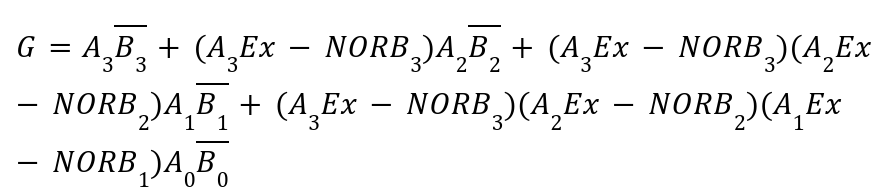
Based on the above statements, the logical expression representing the output G=A > B can be derived as:
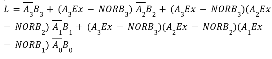
The logical expression representing the output L=A < B can be derived as:
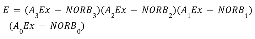
The logical expression representing the output E=A = B can be derived as:
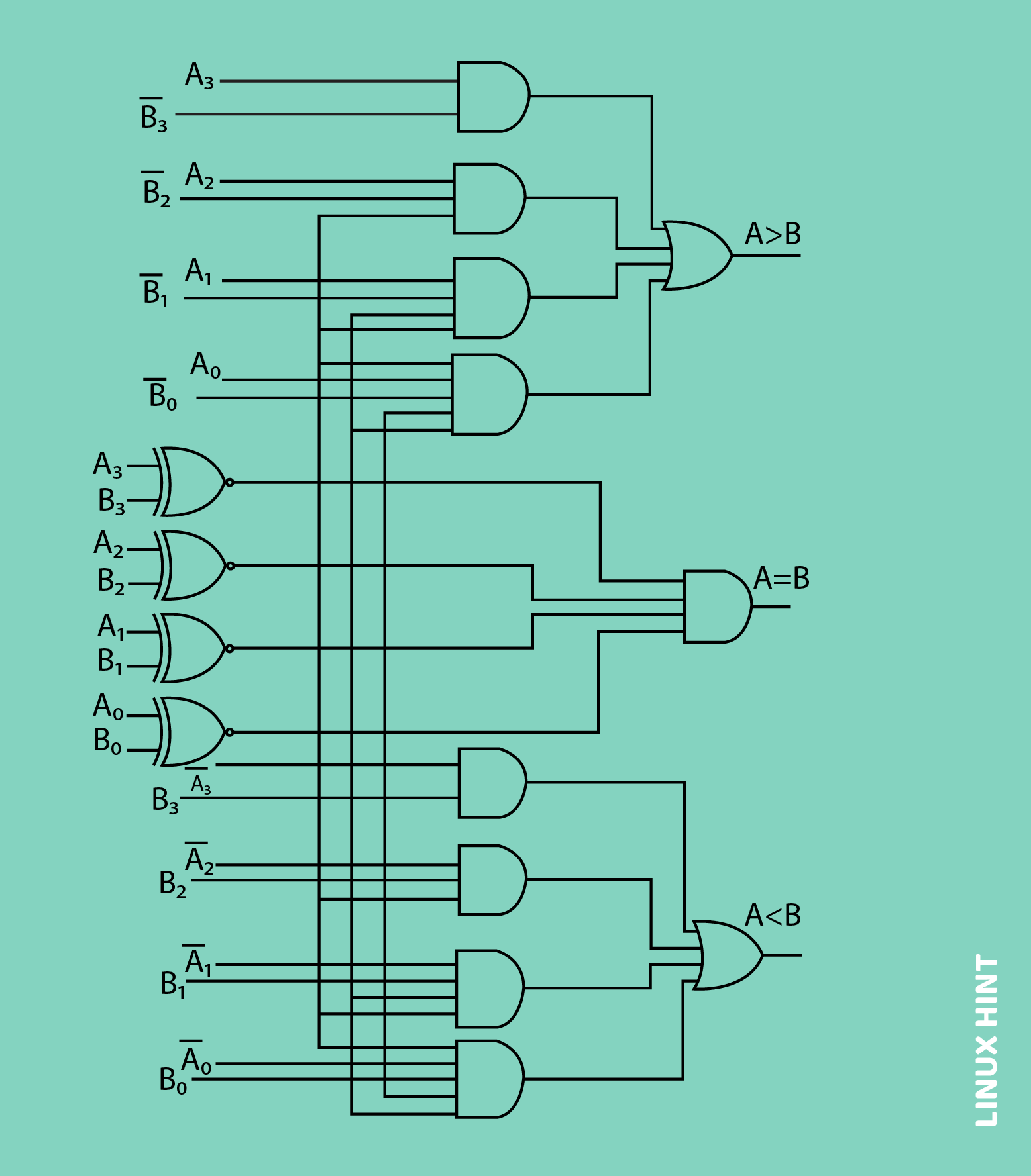
Based on the above outputs of Boolean expressions, the logic circuit for this comparator can be achieved through the utilization of logic gates, as presented below. The binary variable E or A = B is obtained by applying the four outputs from Ex-NOR gates to an AND gate. The last two outputs also utilize Ex-NOR outputs to produce the Boolean functions, as depicted in the below image.
The 4-bit comparator is predominantly found in integrated circuit (IC) form, with the widely used variant being the 7485 IC. This integrated circuit (IC) can be utilized to compare two 4-bit binary words. The two binary words can be compared by grounding the I (A>B), I (AB), and I (A=B) connection inputs to the Vcc terminal. The diagram presented below illustrates the pin configuration of the IC7485 comparator.
8-Bit Magnitude Comparator
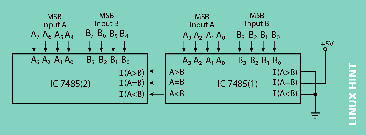
The process of comparing two 8-bit numbers involves the utilization of two 4-bit comparators that are connected in a cascade manner. The circuit diagram of the comparator is presented below, illustrating the interconnection of the lower-order comparator outputs (A<B, A=B, and A>B) to the corresponding cascade inputs of the higher-order comparator.
To properly utilize the lower order comparator, it is necessary to connect the A=B cascade input to a high state, while the remaining two cascading inputs, A and B, should be connected to a Low state. The eight-bit comparator’s outputs are the higher-order comparator’s outputs.
Conclusion
Digital comparators compare two binary values and output results based on whether one number is bigger than the other, equal to the other, or less than the other, according to three different criteria. They are often used as magnitude comparators in performing various arithmetical logical operations.