Regulating and controlling the power transfer in electrical systems is quite crucial because every device must operate normally. Usually, different types of losses occur while supplying power to any device which can affect the system performance. To cater to such issues different devices are mainly used in circuits often called diac, triac, and quadrac.
Diac
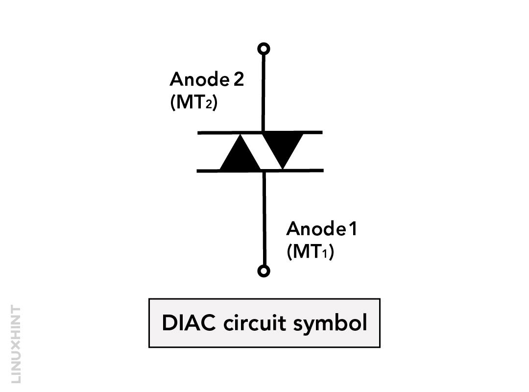
This semiconductor device is a three-layer two-junction semiconductor that acts as a two-directional switch diode. Unlike transistors, this diode does not have any base connection due to which it can be connected in either polarity. The one main property of diac is that it provides an instant trigger pulse and that’s why it is mainly used as a switching device for phase-triggering and power control applications.
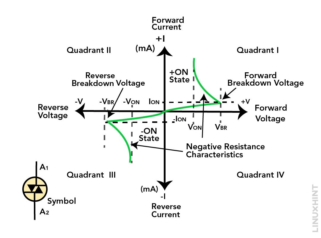
The diac works in such a way that it blocks the current flow until the voltage exceeds the breakdown reverse voltage and once the applied voltage exceeds the diode starts conducting with the abrupt pulse of voltage just like the zener diode. To allow the massive current flow, the resistance of the switch considerably decreases along with the voltage. The breakdown voltage for the diac normally lies in the range of 25 to 35 volts and has a negative resistance characteristic.
Triac
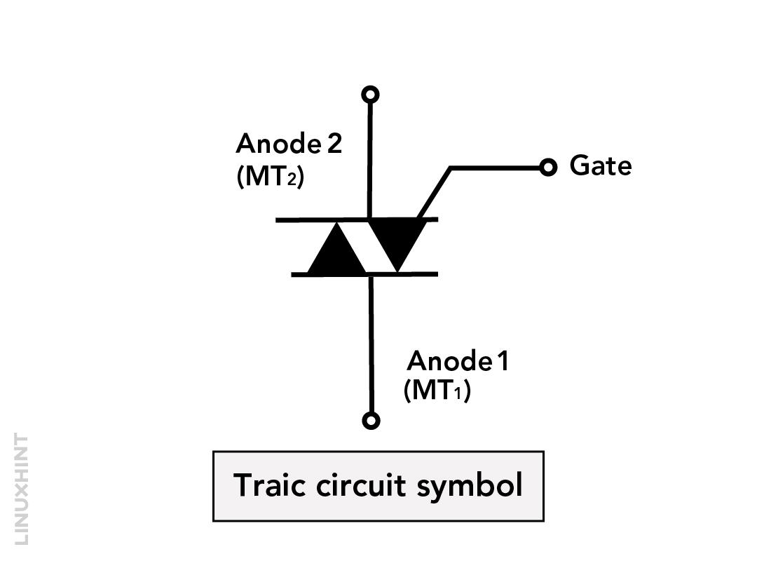
The triac is a four layer three-terminal semiconductor device just like the thyristor, however, the triac has the ability to modulate both halves of the AC waveform. The triac is constructed by connecting two thyristors in reverse order having a common gate. Like diac it can be triggered irrespective of the polarity as it can conduct in both directions.
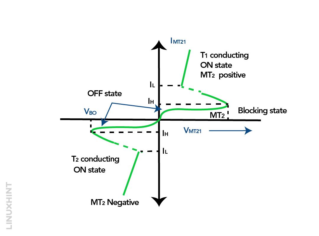
The triac can be triggered normally in two ways one is when the applied voltage exceeds the break over voltage or by giving a pulse for 35 mili seconds. Moreover, it is always recommended to use a resistor with the triac as when it is turned on a high current passes which may damage the device. For power control applications the triac is normally used with diac and this is because the triac firing is not symmetrical which can lead to harmonics generation. Below is the characteristics diagram for the voltage and current of the triac:
In the first quadrant, both the gate terminal and the VMT21 are positive, in the second quadrant the gate terminal is negative. Whereas in the third quadrant both the terminals are negative and in the fourth quadrant the gate terminal is positive and the VMT21 is negative. Here, the VMT21 is the voltage for terminal MT2 with respect to terminal MT1
Quadrac
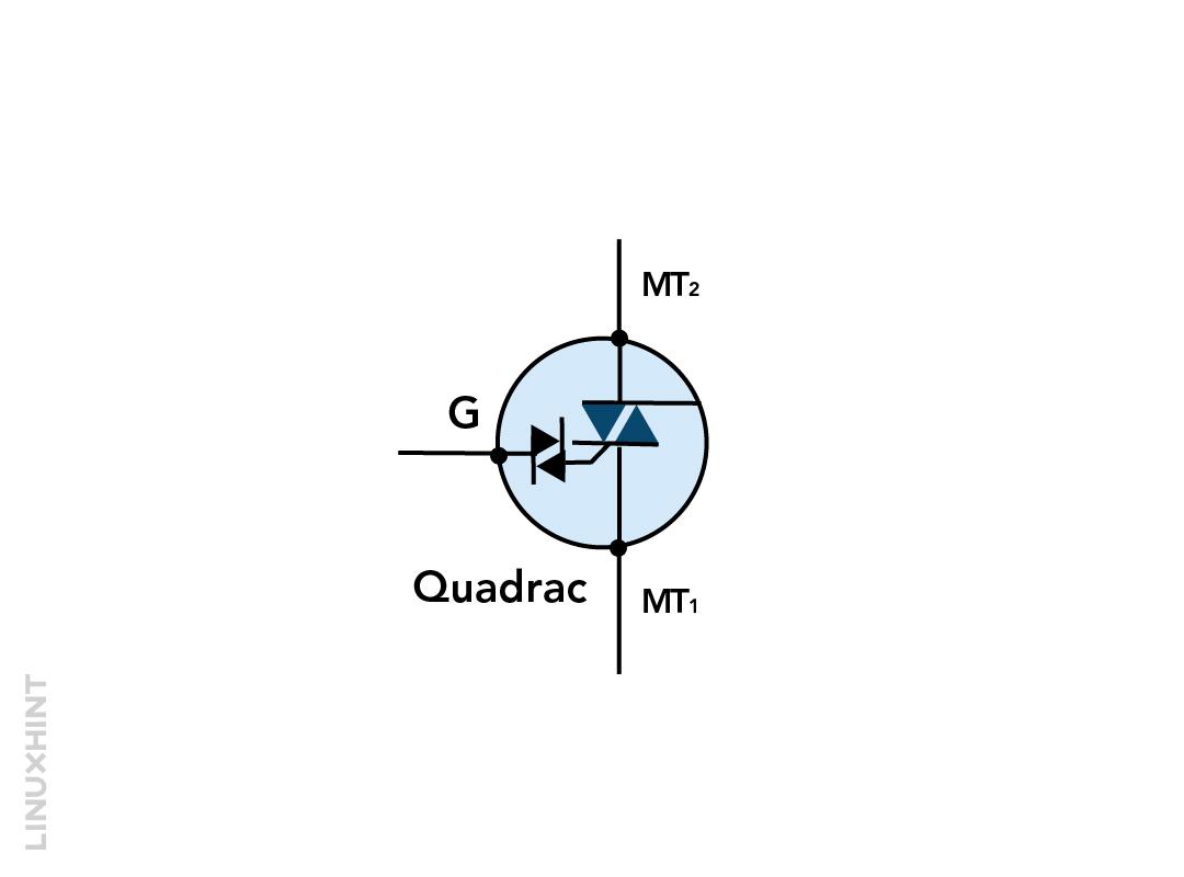
The combination of both triac and diac is referred to as quadrac and this makes it a bi-directional semiconductor that can operate without polarity restriction. These can be used for full wave phase control as in heaters, dimmers, or AC motor speeds. The quadrac is the best replacement for the triac and is available in different packages that are based on different voltage and current preferences but the most popular one is the T0-220.
AC Power Control
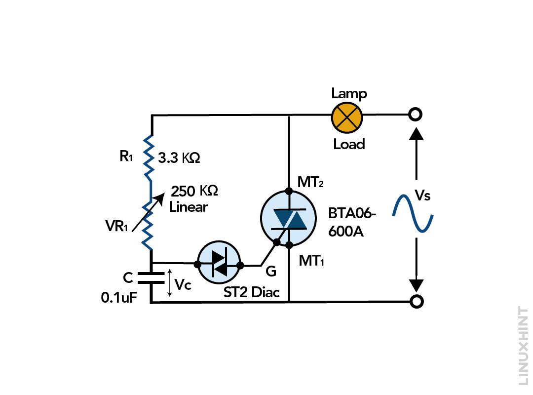
Power regulation is one of the crucial aspects in most electrical systems like controlling motor speeds, brightness of a light, and more. This is necessary because electrical devices work smoothly if the rated power is fed to it that is not less than the desired power nor more than the acceptable range. The diac and triac are normally used for power control, and the combination of both is called quadrac. To illustrate the phase control in an electrical system, here is a simple circuit that uses the lamp as a load, and both the triac and diac are used for the control.
When the supply voltage increases, the capacitor gets charged and crosses the break-over voltage of the diac the capacitor gets discharged through it and as a result the pulse trigger the triac. Once the capacitor starts to discharge with the diac it generates a pulse that triggers the triac. Moreover, the phase angle of triac can be varied using the variable resistor VR1 connected in series with the capacitor.
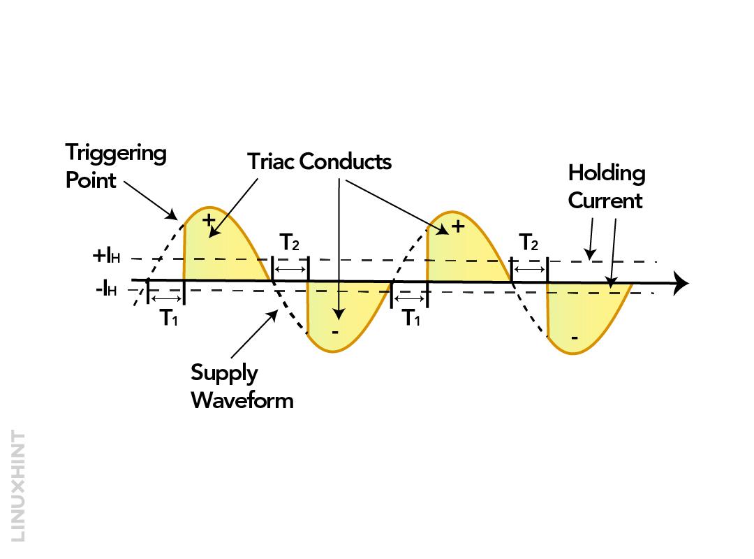
This way, the bulb light intensity can be adjusted and the R1 resistor is connected to keep the current at a safe value if the variable resistor is at its minimum value. The triac will remain in conduction due to the load current flowing through it, the voltage across the capacitor and the resistor is kept till the first half cycle of the AC supply.
After the first half cycle, the triac goes to the OFF state when the current falls below the holding current and the voltage supply drops to zero. In the second half cycle the voltage again begins to rise up however the direction will be opposite.
Conclusion
The diac is primarily used as a triggering device, whereas the triac is used as a controlling device in applications like controlling the motor speed, controlling the light intensity of the bulb, chopper circuits, phase control, and more. The diac is mainly used with the triac because of its fast triggering response, which prevents harmonics generation, and the combination of both is known as quadrac. For AC power control, when the supply voltage exceeds the diac break-over voltage it triggers the triac, and it goes into conduction.

