Triacs are used as bidirectional switching electronics circuits used in a wide variety of applications. They can be used to switch different AC-based applications such as motor drives, motor speed controllers, and frequency controllers. This article describes triac switching circuits in detail.
TRIAC
The term ‘TRIAC’ can be split into two words, triode and AC. The triode means three terminal switching devices. AC corresponds to the alternating current, as triacs are bidirectional and most suited to alternating current-based switching applications. The construction of triac shows the interconnection of two SCRs in an antiparallel direction, as shown below:
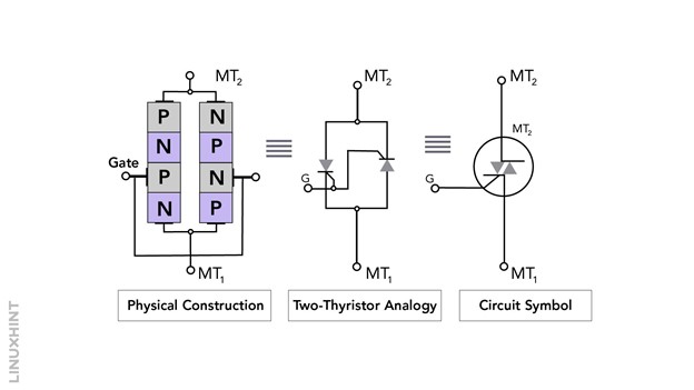
Due to bidirectional characteristics, the current can enter from MT2 terminal and exit from MT1 terminal. On the other way round, the current can enter from MT1 terminal and exit from MT2 terminal. The operation of the triac takes place when the gate voltage has been applied.
Operational Modes and V-I Characteristics
A positive or negative pulse can be applied to the gate terminal depending upon the type of gate pulse and terminal voltage to trigger it, triac can operate in four of its operational modes:
-
- Positive Voltage at MT2 with Positive Gate Pulse
- Positive Voltage at MT2 with Negative Gate Pulse
- Negative Voltage at MT2 with Positive Gate Pulse
- Negative Voltage at MT2 with Negative Gate Pulse
The four of the operational modes are shown in the V-I characteristics curve of triac:
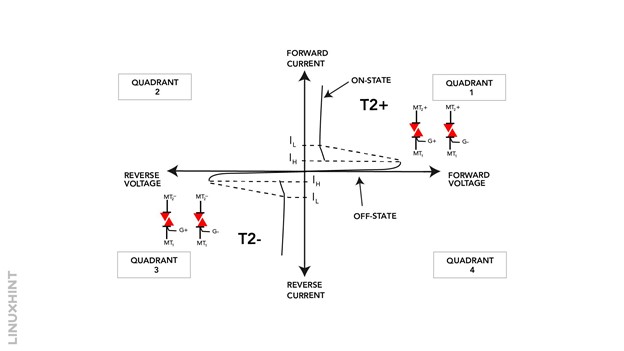
For turning the triac ON, either a positive or negative gate pulse is required. The triac conducts when either one of the two SCRs is turned on. In case, if MT2 terminal is negative while MT1 terminal is positive, the second SCR turns ON and in case if MT1 terminal is negative while MT2 terminal is positive, the first SCR is turned ON.
Threshold Gate Voltage VGT and Threshold Gate Current IGT
There is a minimum level of gate voltage that should be applied to turn ON the triac and is called threshold gate voltage. Similarly, The minimum level of gate current for triggering the triac is called threshold gate current. The duration of time that a triac takes to convert from off state to on state as soon as the gate is triggered is called its turn on time.
Latching Current IL and Holding Current IH
There are two types of currents involved during the conduction operation of triac; latching current and holding current. A triac remains ON once the gate has been triggered, even if the gate supply has been removed. However, it requires load current to be greater than the specific level of current called the latching current to remain in the ON state. There is a minimum current level defined for triacs as well that is required for operating triac known as holding current.
Forced Commutation
For turning the triac OFF, the load current through it is reduced below the level of holding current. This technique is called force commutation, while the circuits involved in turning off the triacs are called commutation circuits.
Triac Switching Circuit with DC Supply
A simple triac-based switching circuit for a lamp is shown below. When switch SW1 is open, no current flows to the gate terminal and the triac remains in OFF state. When switch SW1 is closed, gate current applies at the gate terminal from the battery source through a resistor, which turns ON the triac.
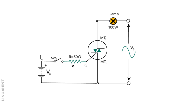
The limitation in the above arrangement is that only a positive gate pulse can be applied, as the positive plate of the battery has been connected to the gate terminal. Therefore, only positive gate pulse-based operational modes can be achieved in this configuration. In other words, triac can operate in the first and third quadrants of its V-I characteristics.
Triac Switching Circuit with AC Supply
The triac switching circuit with sinusoidal AC supply to the gate terminal is shown below:
This configuration overcomes the limitations of DC supply-based switching circuits. It operates on the same principle of switching ON and OFF the switch SW1. When switch SW1 is open, it does not conduct and when switch SW1 is closed, it starts to conduct.
However, in this case, triac current falls below the latching current when the load current cycle reaches zero value, resulting in its unlatching mode. During the negative half, the second thyristor is switched ON due to the reverse polarity of the sinusoidal input.
Modified Triac Switching Circuit for Half to Full Power Supply
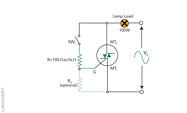
This triac configurations provide three-way switches for triggering gate terminals as shown below:
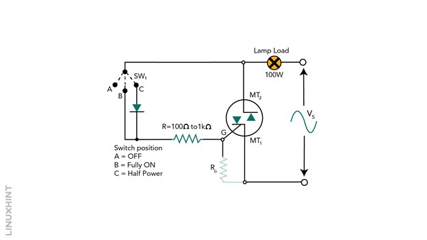
When the switch is at position ‘A’, no current is supplied, and the triac remains OFF. When the switch is at position ‘B’, the triac operates in two of its operational modes (Positive Quadrant I and Negative Quadrant III) as a gate pulse is applied to MT1 terminal as in that of DC case. When the switch is at position ‘C’, a diode is added to the triggering circuit, with its ends connected to MT2 and MT1. In case MT2 is at a negative potential, the diode is reverse biased, and the triac will not be triggered. Therefore, the negative operational mode has been eliminated and triac operates only in its first Quadrant positive mode.
Conclusion
AC power control and AC-based power switching can be most efficiently utilized through triac switching circuits due to their bidirectional nature. They can provide full-cycle control for different resistive and inductive loads.