Demultiplexers or data distributors distribute single input signal into multiple outputs. They are exactly in opposite to the operation principle of multiplexers which take multiple inputs and produce single output. They may also be called ‘Demux’ in shorter form. This article describes de-multiplexers in detail.
Demultiplexer
The De-multiplexer has single input lines that provide the information, which is then sent to the output line. There is a total of 2n potential input combinations in de-multiplexers. Demultiplexers including the following types:
-
- 1x 4 Demultiplexer
- 1x 8 Demultiplexer
- 1x 16 Demultiplexer
These are discussed in detail below.
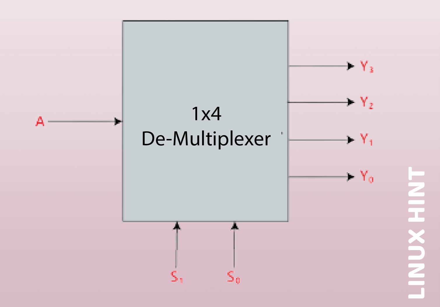
1×4 Demultiplexer
In a 1 to 4 De-multiplexer, there is just one input, two selection lines, and a total of four outputs. The outputs are based on the inputs combination that are present at the two selection lines.
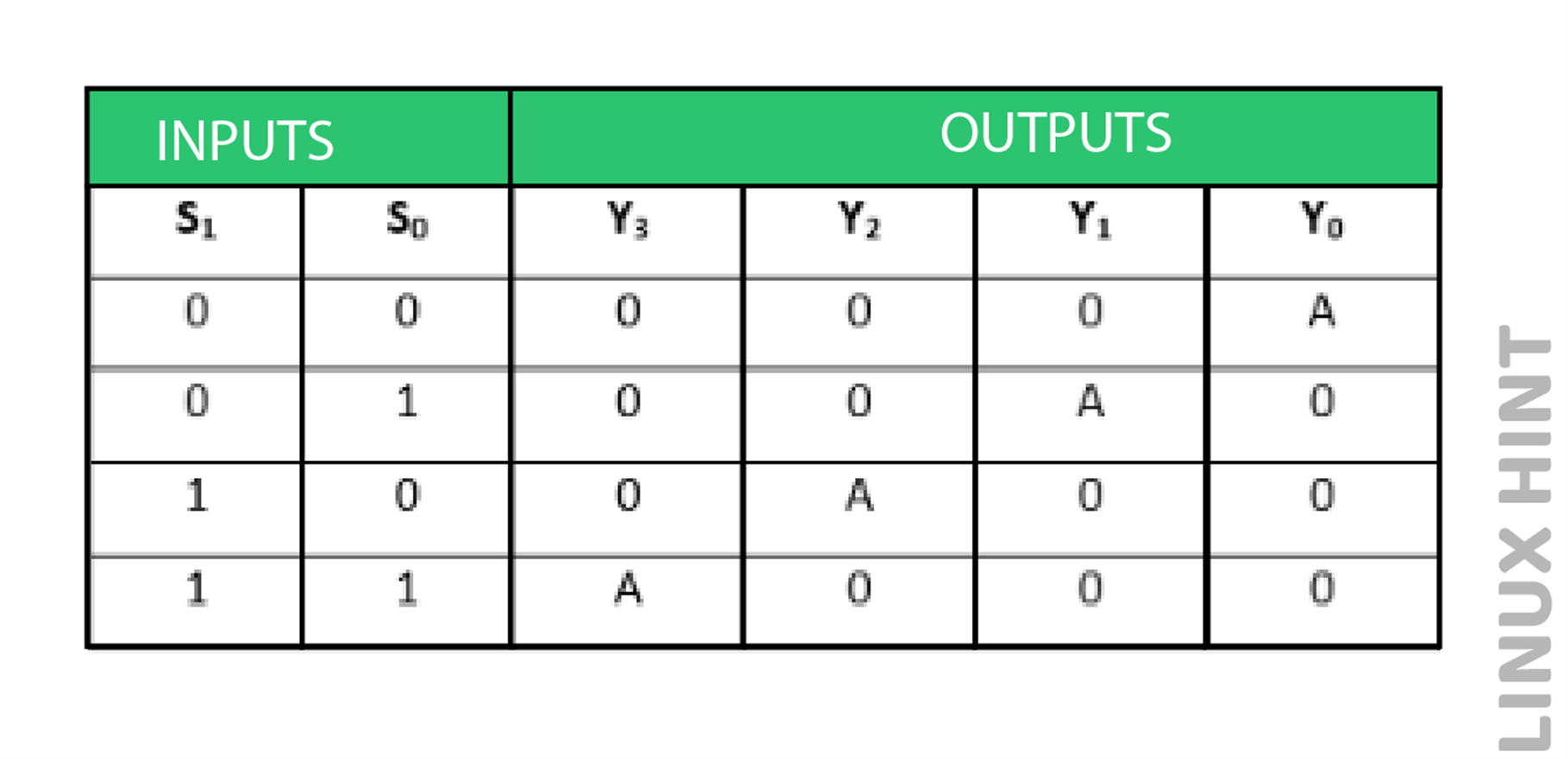
Truth Table
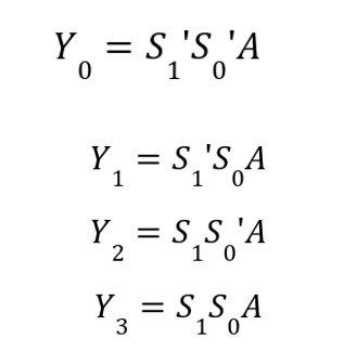
Logical Expressions
The following are the logical expressions for outputs:
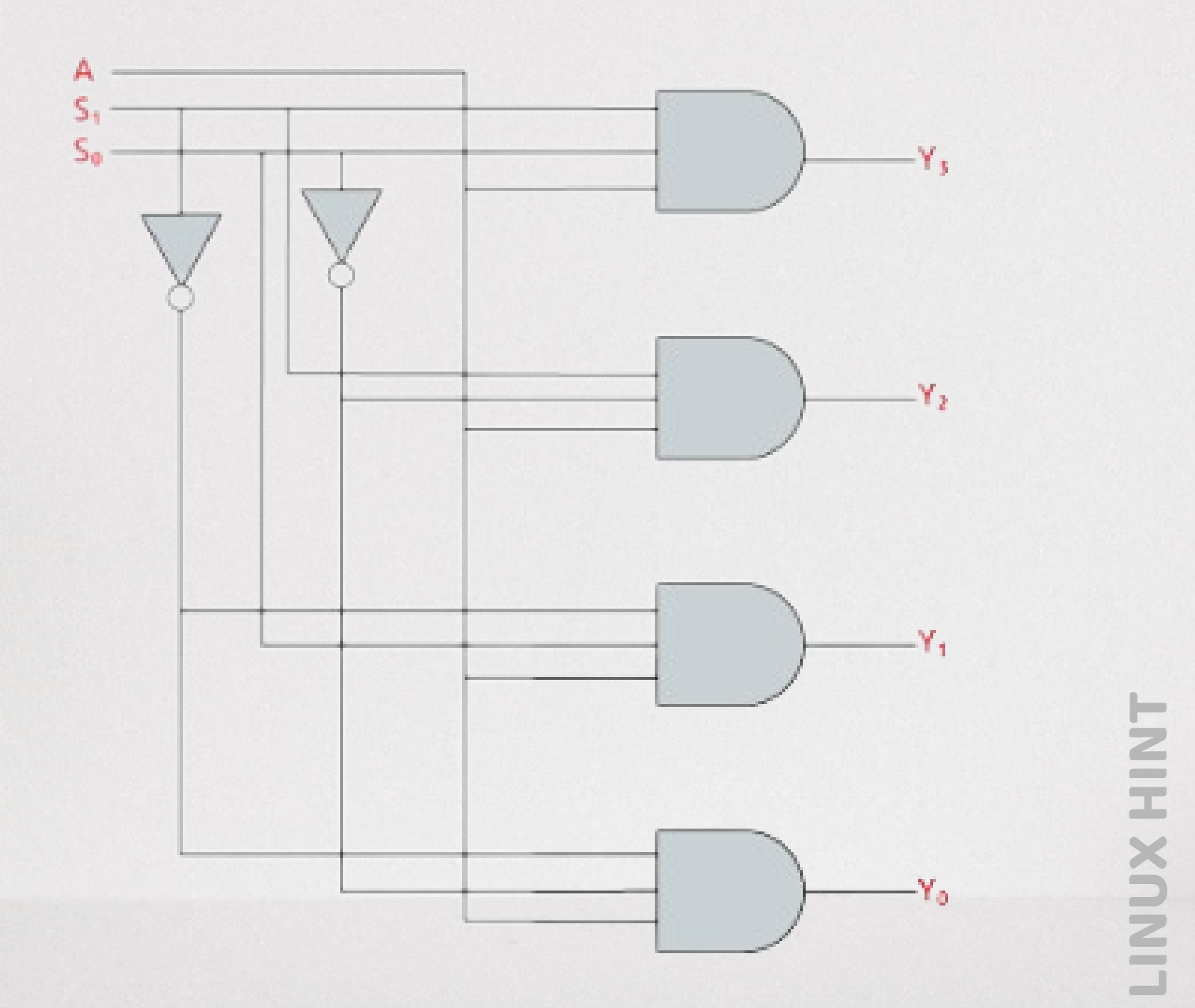
Logic Circuit Diagram
The following is the logical diagram based on above truth table:
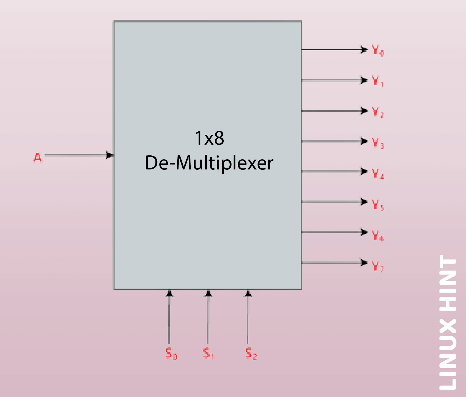
1×8 Demultiplexer
Eight outputs, three selection lines and a single input make up the 1 to 8 Demultiplexers. The outputs are based on the inputs combination that are present at the two selection lines.
Truth Table
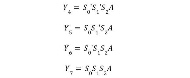
Logical Expressions
The following are the logical expressions for eight outputs:

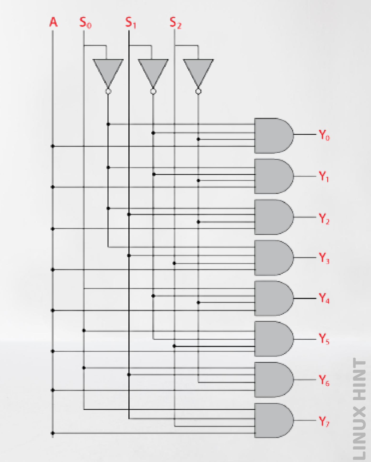
Logic Circuit Diagram
The following is the logical circuit based on above truth table:
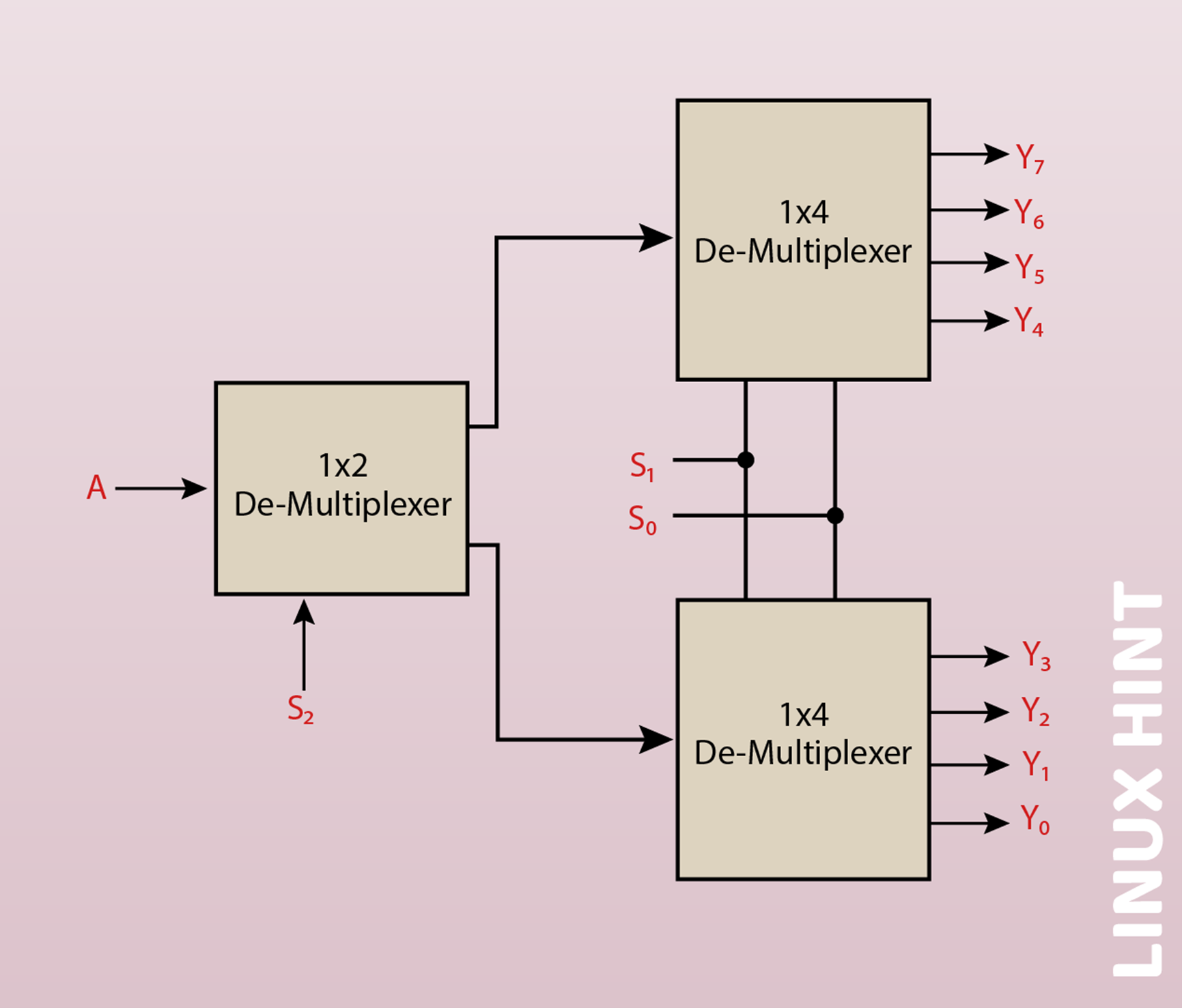
1 x 8 De-multiplexer utilizing 1×4 and a 1×2 demultiplexers
A lower order de-multiplexer may be used to implement the 1×8 de-multiplexer. Two 1×4 de-multiplexers and a 1×2 de-multiplexer are required to implement the 1×8 de-multiplexer. The 1×4 multiplexer has 1 input, 4 outputs, and 4 selection lines. There is just one selection line on the 1×2 demultiplexer.
We need two 1×4 de-multiplexers to get 8 data outputs. Two outputs are produced by the 1×2 demultiplexer. Therefore, the outputs of the 1×2 de-multiplexer must be fed to the 1×4 de-multiplexer in order to get the requisite output.
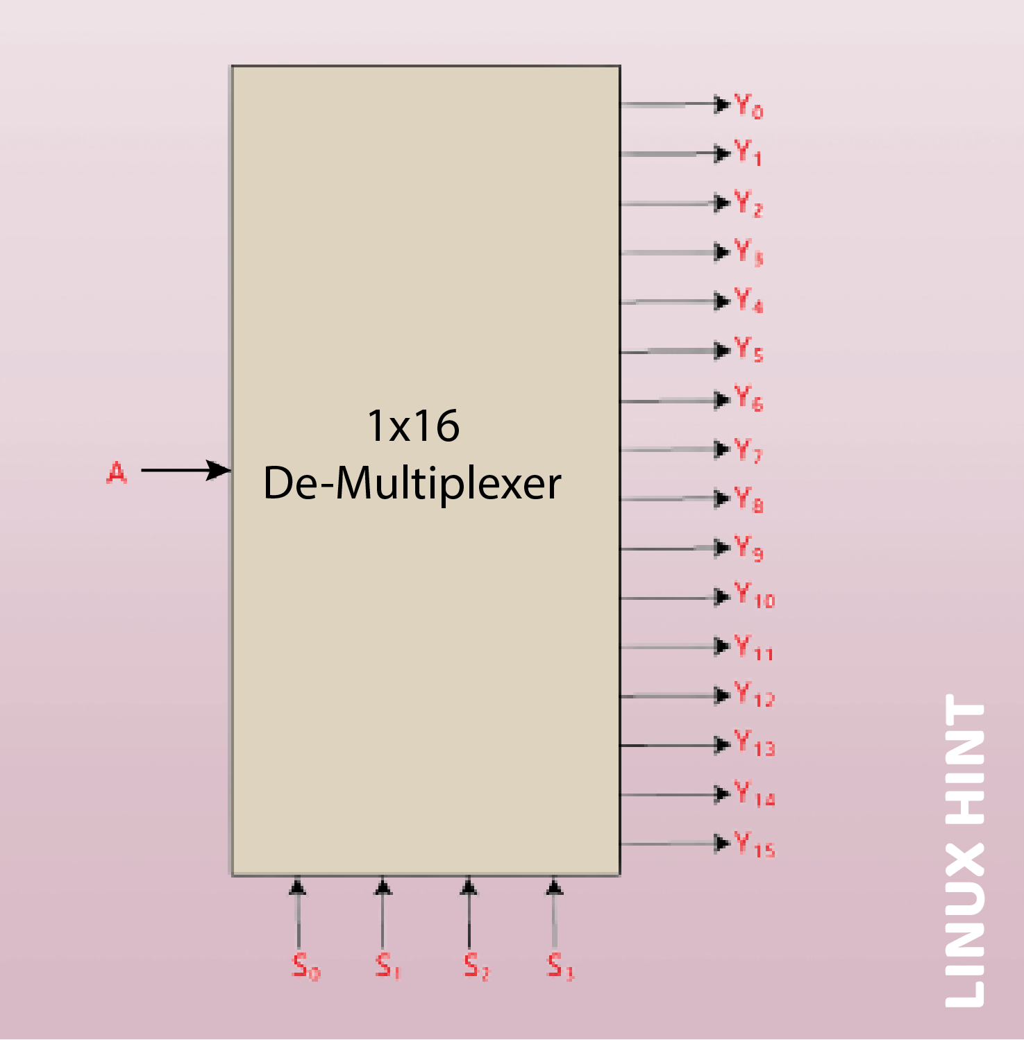
1x 16 Demultiplexer
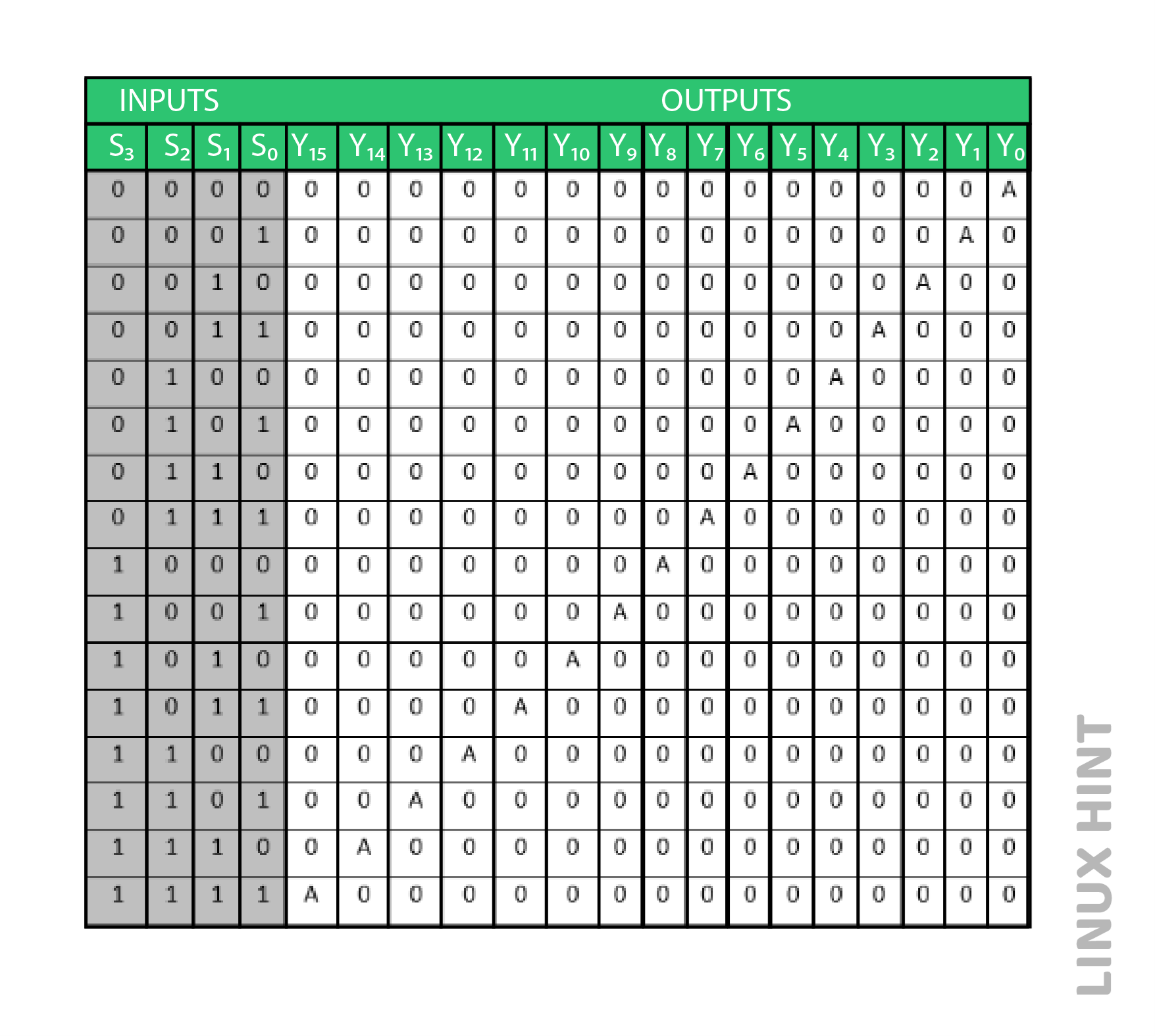
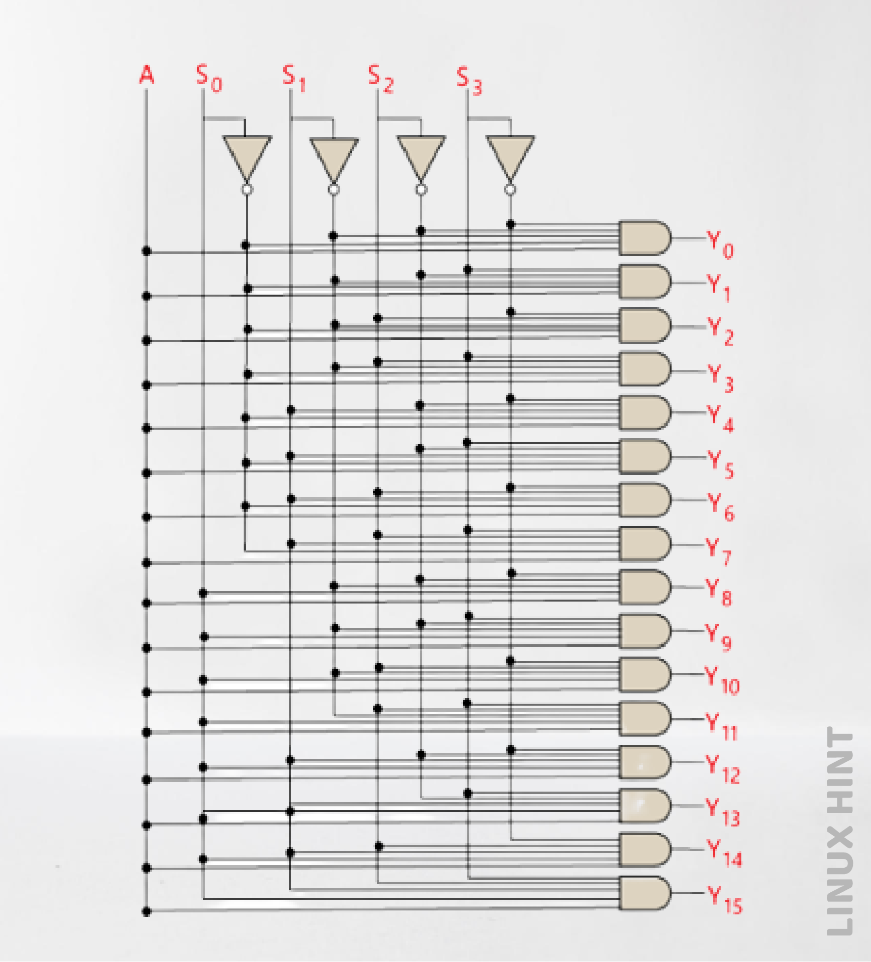
The 1×16 de-multiplexer has a single input, A, four selection lines and a total of 16 outputs. The outputs are based on the inputs combination that are present at the two selection lines.
Truth Table
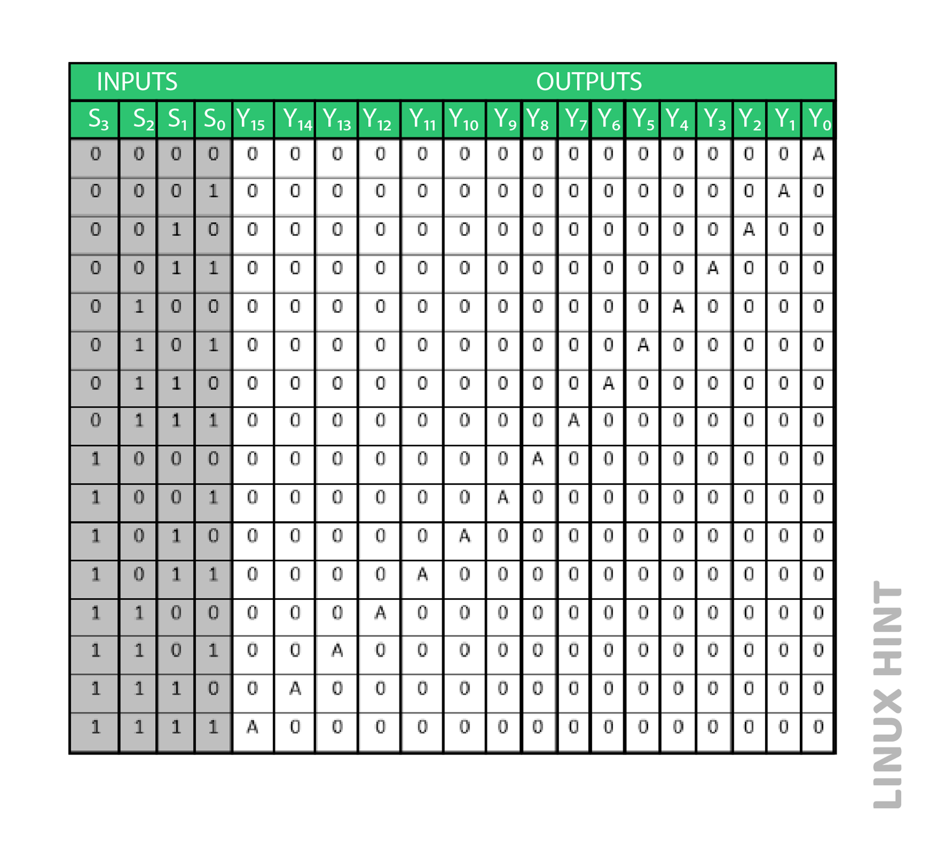
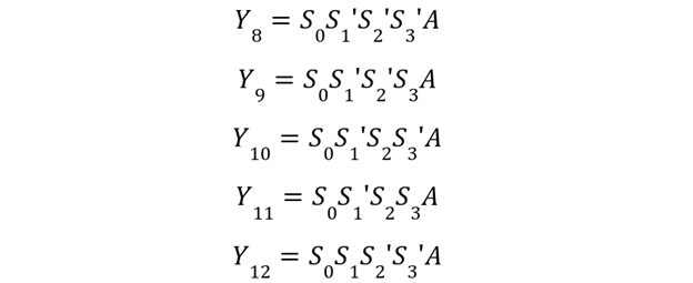
Logical Expressions
The following are logical expressions for the outputs:


Logic Circuit Diagram
The following is the logical circuit diagram based on the above truth table:
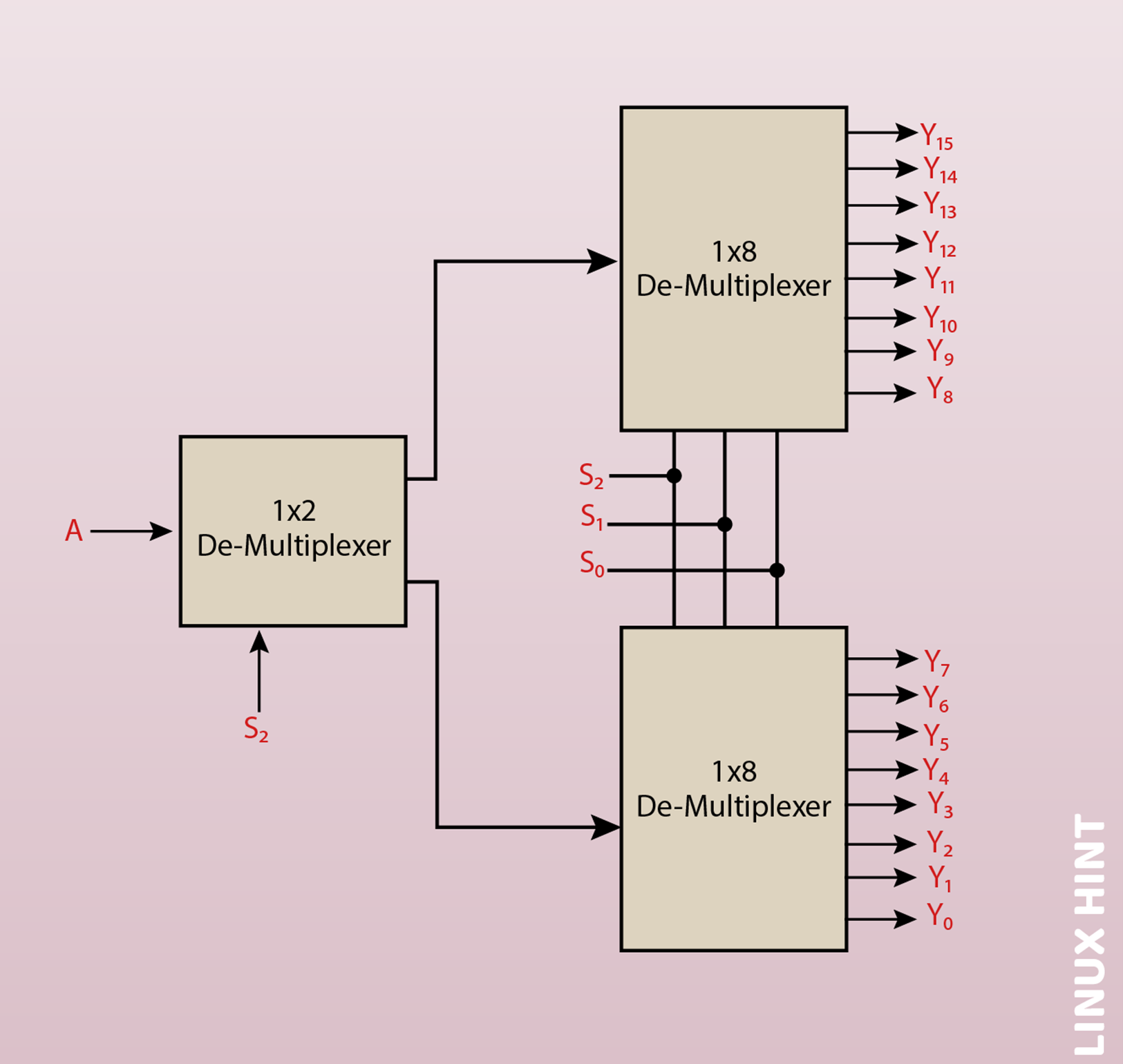
1×16 Demultiplexer Utilizing 1×8 and 1×2 Demultiplexers
A lower order de-multiplexer may be used to implement the 1×16 de-multiplexer. Two 1×8 de-multiplexers and a 1×2 de-multiplexer are required to implement the 1×16 de-multiplexer. Three selection lines, one input, and eight outputs make up the 1×8 multiplexer. There is just one selection line on the 1×2 demultiplexer.
We need two 1×8 de-multiplexers to get 1×6 data outputs. Eight outputs are produced by the 1×8 demultiplexer. We thus need a 1×2 de-multiplexer to generate two outputs from a single input in order to get the final result. The de-multiplexer will then receive these outputs as input. Below is a block diagram of a 1×16 de-multiplexer employing an 1×8 and 1×2 de-multiplexer.
Conclusion
Demultiplexers take N input lines and produce 2N output lines. The single input data can be transferred to multiple output lines based upon the selection made for the chosen outputs. They are used in applications for memory decoding, data routing, data transmission and acquisition systems.