DC Circuit Theory
Atoms are the building blocks of every material. They are composed of subatomic particles which are called neutrons, electrons, and protons. Protons and neutrons are located within nucleus, while electrons revolve around the nucleus and form the outer part of atoms. Protons have a positive charge, while electrons possess a negative charge.
Atoms are stable in a normal state and their subatomic particles are located within their normal positions inside atoms. However, when these atomic particles receive a force or energy from outside, the structure does not remain the same. Some of the electrons are detached from outer shells.
If we connect these atoms in the wire of an electric circuit, these loosely bound electrons will start to move across the wire, which is called electric current. The wire material is not perfect, and it offers some limitations to freely moving electrons, and this ability of limiting current is called resistance of material.
The movement of electrons between any two different points can be controlled in an electrical circuit. The driving force responsible for this movement is called potential or voltage.
Finally, DC circuit theory deals with direct current electrical circuits. Direct current can be understood as unidirectional flow of free electrons. These free moving electrons cannot change their direction in any case. DC circuit theory revolves around three basic parameters: voltage, current and resistance.
Electrical Voltage
Electrical voltage is defined as the driving force that moves electrons between two different points in an electrical circuit. It can be understood as an energy moving electrons in an electrical circuit. These two points in an electrical circuit shall have different energy levels of electrons. It implies there is a difference in voltage in an electric circuit. This energy level difference is called a potential difference or voltage difference.
Units of Electrical Voltage
Units mean the measurement scales. The unit of electrical voltage is ‘volt’. For large voltages, adding a number of zeros may add complexity and therefore prefixes are used. Prefixes define different multiples of zeros, from two zeros to nine zeros, and so on. Similarly, small voltages can also be present in multiples.
For 1000V, the prefix of kilovolt is used. It means 1000V=1kV. Similarly, for small values comprising three zeros after decimals like 0.0001V can be represented with millivolt. It means 1mV=0.000V.
Examples
DC voltage sources are batteries and solar cells. DC Batteries are normally in 12V or 24V ranges. AC sources are more common, and they provide 230V voltage to run our domestic appliances.
Representation
Different representations are used to identify AC voltage source, DC voltage source, single cell battery or multiple cell batteries. They are shown below:

Electrical Current
The movement of free electrons between two different points in an electrical circuit is known as electric current. This movement is often controlled by driving and a controlling force called voltage. The voltage difference controls whether large or small movement of electrons will occur between two points.
Unit of Electrical Current
The unit of electrical current is ‘ampere’. If a large amount of current is to be mentioned, the number of zeros shall be replaced with prefixes of kilo, mega, giga and so on for large values. Similarly, for smaller values, units of milli, micro, nano shall be used. For 1000A, we can use 1 kiloampere. For 0.0001A, we can use 1 milliampere.
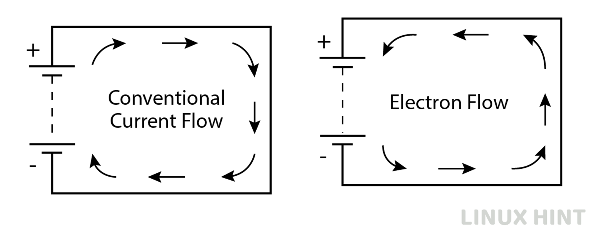
Conventional Current Flow and Electron Flow
In practical cases, electrons are negative charges, so they move from the negative terminal of batteries into positive terminals. However, in electrical circuits presentation, the method of showing flow of electric current is opposite. Conventional current flow is shown to start from the positive plate of the battery to the negative plate. These concepts ease up the calculations and theorems applied to electrical circuits. Therefore, conventional current flow is adopted in defining all electrical networks. The difference between the two has been presented below:
Representation
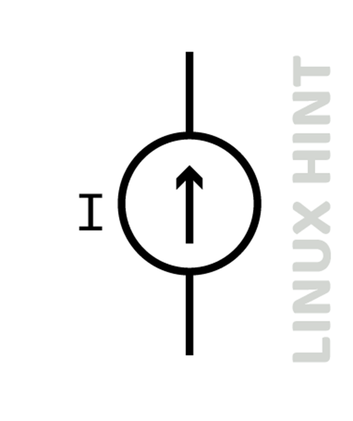
Current sources are presented by a circle with arrow-drawn inside the circle to indicate direction of current as shown below:
Electrical Resistance
It is the ability of electrical material to limit the electric current passing through it. Due to the opposition, it is called resistance. The resistance of every material is different. Some materials have high opposition ability, called high resistance materials. Some have intermediate resistance, and some have very low resistance.
Electrical Units
The units of electrical resistance are ohms. It is presented by the symbol Ω. High resistances can be presented by prefixes of kilo, mega, giga, while low resistances can be presented by prefixes of milli, nano and micro. So, 0.000001Ω is represented as 1 microohms or 1uΩ. Similarly, the resistance with 1000Ω can be represented in the prefix of kilo as 1kΩ.
Representation
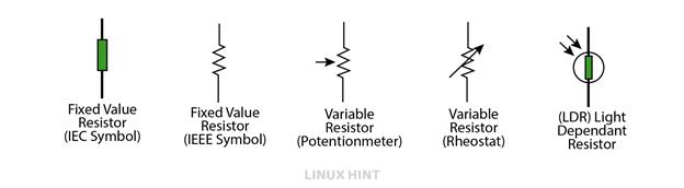
Resistance can have fixed value, variable values, or they can take the form of light emitting resistors. The representation to differentiate resistances is shown below:
Basic Electrical Circuit
A basic DC electrical circuit with parameters of voltage, current and resistance is shown below:
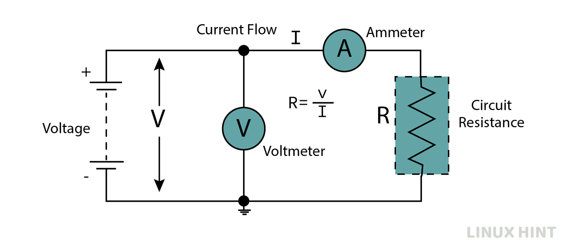
A multi-cell battery shown with more than two plates acts as a DC source. An electrical resistance is connected in this circuit. Two meters are used to measure electric current and electric voltage.
Relationship between Basic Electrical Parameters
If we plot the voltage on x-axis and current on y-axis, we can get a linear trend on the graph. It means increase in voltage, increase current. So, both x-axis and y-axis values increase, and a linear rising pattern is obtained as below:
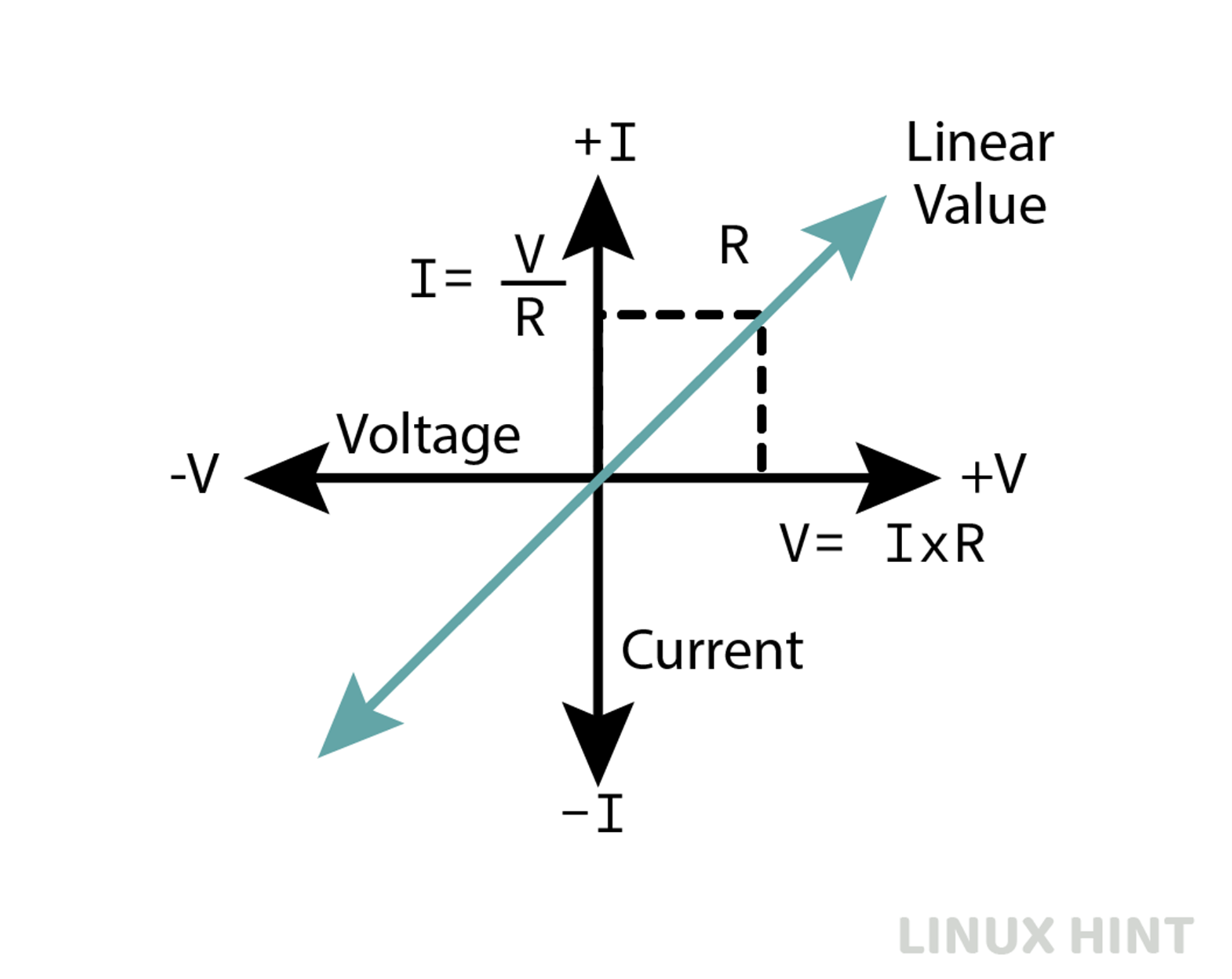
Slope at any point of this graph provides the value of resistance.
DC Series Circuit
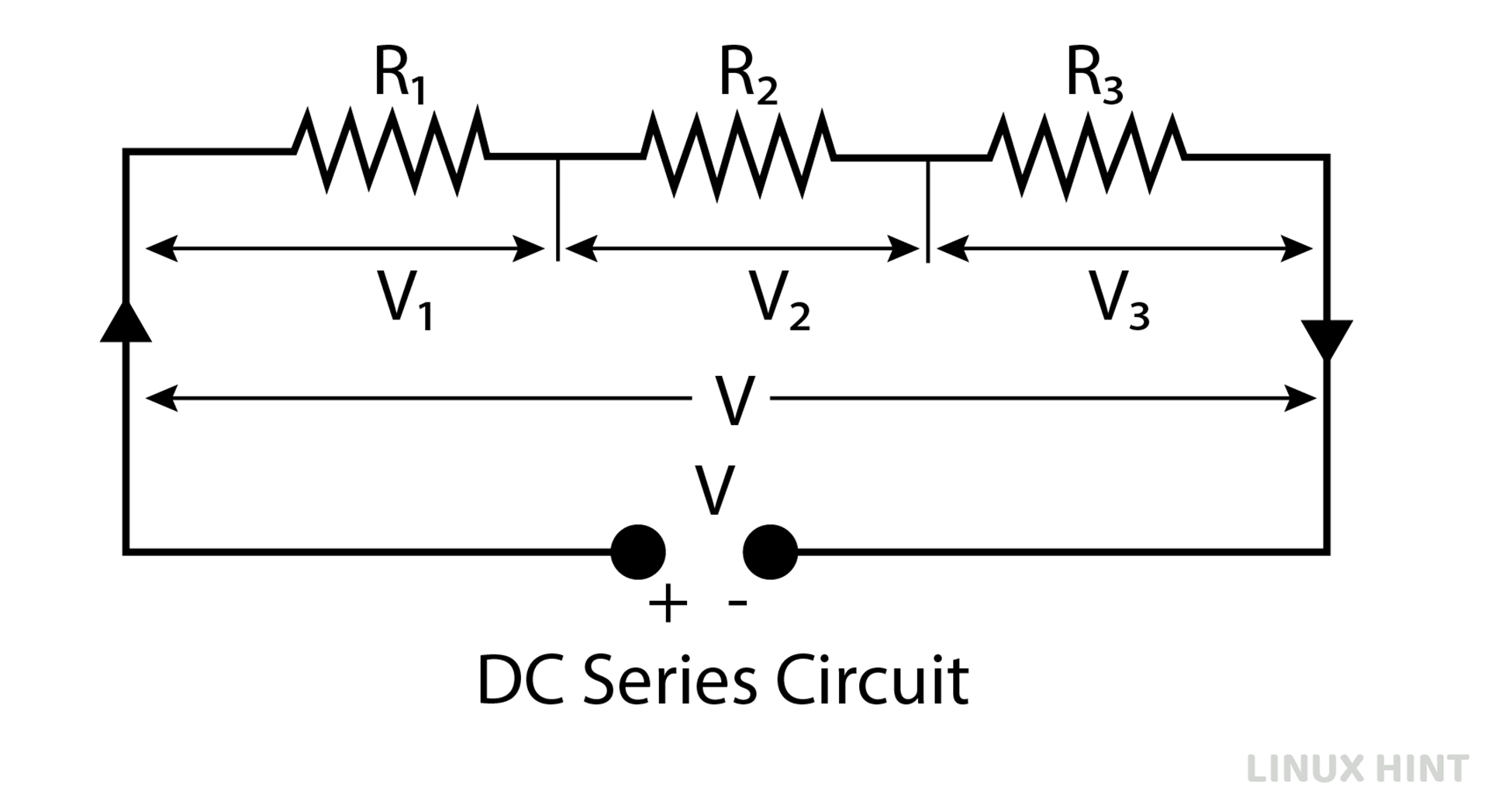
When resistances are connected from end to end in an electrical circuit and supplied with a DC supply, this configuration is called DC series circuit. In figure below, three resistances R1, R2 and R3 are connected in series and their voltage drops have been mentioned as V1, V2 and V3.
![]()
By standard ohm’s law equation:

DC Parallel Circuit
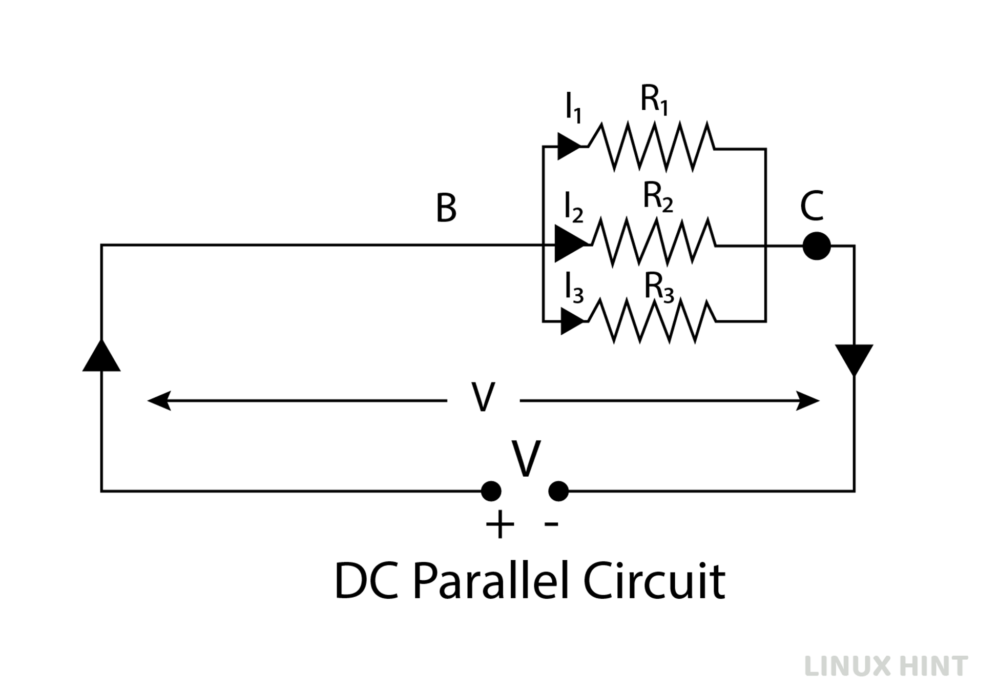
When resistances are connected in such an arrangement that they have a common first point and last point and supplied with a DC supply, this configuration is called DC Parallel circuit. In the figure below, three resistances R1, R2 and R3 are connected in parallel, and their voltage drops have been mentioned as V1, V2 and V3.
![]()
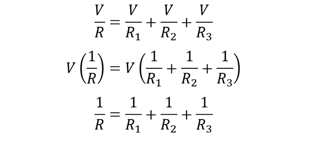
By standard ohm’s law equation:
Ohm’s Law of Basic Electrical Parameters
Ohm’s law is basic electrical law providing the mathematical relation between basic electrical parameters. It is given by:
![]()
Current is therefore a function of voltage and resistance:
![]()
Resistance is therefore a function of voltage and current:

Conclusion
DC circuit theory provides the fundamental concepts of electricity and electrical networks. The theory describes the three basic parameters of voltage, current and resistance. The relationship between voltage and current plot for fixed resistance value is a linear rising pattern.