Current Transformers (CTs)
Current transformers (CTs) are specialized electrical instruments utilized for the measurement and monitoring of alternating current (AC) or the detection of elevated current levels in power systems. These instruments perform an essential function in ensuring the protection and enabling precise metering applications. By effectively reducing high current values to a standardized level, CTs ensure the safe execution of measurements and enable the proper operation of interconnected devices in the system.
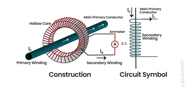
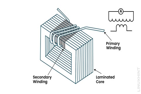
The primary winding consists of a single turn of large cross-sectional area connected in series with the high current carrying conductor. The secondary winding comprises many turns of small cross-sectional area. The secondary coil is connected with a normal ammeter for current measurements.
Working Principle of Current Transformer
Current transformers utilize the principle of electromagnetic induction to function effectively. These devices consist of two vital elements: primary and secondary winding. The primary winding is interconnected in series with the high-current circuit, generating a magnetic field proportional to the flowing current.
In contrast, the secondary winding is linked to devices used for measuring or providing protection. It is intentionally designed with a distinct number of turns compared to the primary winding, establishing the transformation ratio. Consequently, the secondary winding generates a current that accurately reflects the proportionality of the primary current.
Current transformers are basically step-up transformers which increase voltage and decrease current in the secondary winding.
For transformers, the ratio of secondary and primary current equals the ratio of turns in primary and secondary winding, as given by:
In the current transformer case, the turn’s ratio is quite high and therefore the ratio between secondary and primary currents is significantly high.
The CT ratios are generally in the orders of 500:2, 200:1. The CT ratio 500:2 implies the conversion from primary current of 500A to secondary current of 2A.
Types of Current Transformer
Current transformers have different variations based on the type of construction and insulation. They are classified into two broad categories: indoor and outdoor types.
Indoor Current Transformer
Indoor current transformers are used indoors, and they can be divided into three major types based on construction:
1: Bar Type CT
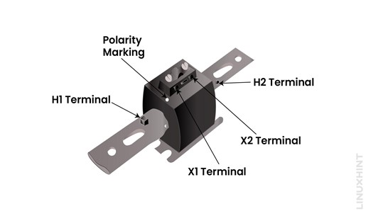
These current transformers use metallic bars as primary winding and therefore called bar type current transformers.
2: Slot/Window/Ring Type CT
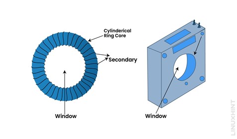
These current transformers are hollow shaped, and the primary conductor is placed inside out this opening:
3: Split Core Type CT
It is a special type of current transformer that can split open into two parts. This kind of arrangement can provide easy access to open up the structure and windings.
3: Wound Type CT
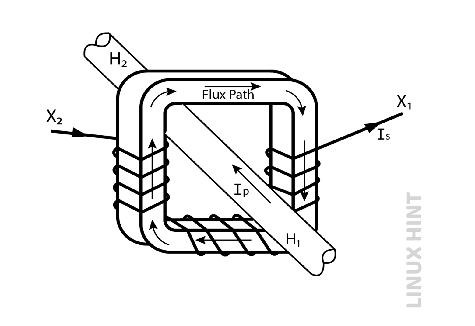
Primary windings of these current transformers are wound around the central core. The number of turns shall be any number greater than one.
Indoor current transformers can also be divided on the basis of insulation; these include tape insulated current transformers and cast resin insulated current transformers.
Outdoor Current Transformer
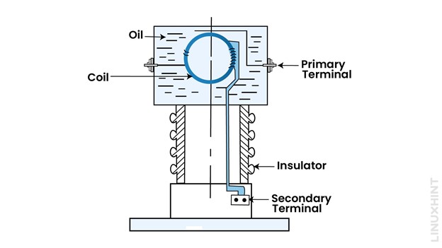
Outdoor current transformers are installed outdoors, and they can be divided on the basis of their working principle. As these are outdoors, they require both insulation and cooling for their operation. Mostly, transformer oil is used as an insulation medium. Oil-filled current transformers are further classified as below:
1: Live Tank Type CT
Live tank means the tank of CT is kept at system voltage. The gravity point is located at height.
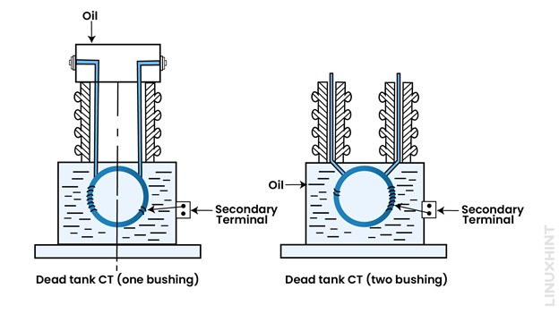
2: Dead Tank Type CT
Dead tank means the tank of CT is kept at earth potential. The gravity point is lower than in Live tank CTs.
Measurement Current Transformer
These current transformers are used only for metering and indication purposes. Measurement type current transformers are designed for accuracy in measurement functions within the rated current. As soon the current exceeds rated limits, metering CTs get saturated to limit any more current into it. However, metering CTs have lower burden values as compared to protection current transformers. A metering class CT is mostly represented by three parameters.
These parameters include accuracy, metering class and burden of current transformer. Below CT has 0.3% of error limit, metering class denoted by ‘B’ and load of 0.9 Ω.
Protection Current Transformer
These current transformers are used only for protection functions. These CTs operate over a wide range of both rated and fault currents. Protection CTs therefore exhibit linear response for up to 20 times of their rated current level. Protection current transformers are denoted by their ‘C’ values which indicates the error ratio and terminal voltage values.
For C class CTs, the error limit is below 3%, standard burden of 2Ω, secondary voltage of 200V.
Current Transformers Turn Ratio
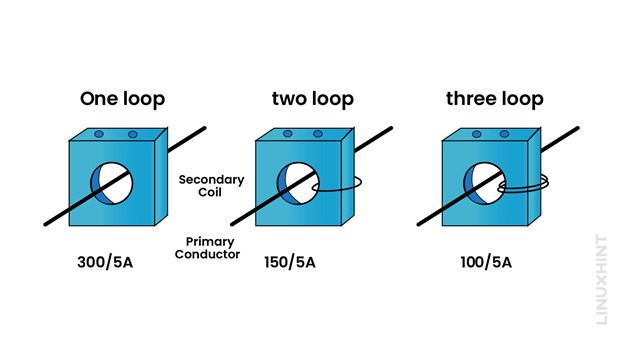
Higher current transformer ratios are convertible into smaller ones by modifying the number of loops in the primary coil. Consider a normal construction of 300/5A CT, where a single primary coil loops across the window known as one pass CT. The same can be re-configured by passing the primary coil two or three times across the window known as two or three pass CT.
With two passes of primary coil, 300/5A can be converted to its equivalent 150/5A CT. Similarly with three passes of primary coil, 300/5A can be converted to its equivalent 100/5A CT.
Example: Calculate Secondary Current and Voltage
Consider a Bar CT with five primary turns and 300 secondary turns to be used in conjunction with an ammeter of internal resistance 0.5 ohms. Ammeter should provide full scale deflection when primary current reaches 1000A.
The secondary current is given by:
Calculating voltage through ohm’s law:
Conclusion
Current transformers are instrument transformers used for measuring high magnitude currents that cannot be measured by standard ammeters. Current transformers provide both measurement and protection functions in electrical networks.

