Voltage control is often accomplished using a variable voltage power supply. LM317 IC’s capabilities include internal current regulation, overload protection, over-voltage protection, and many more. LM317 voltage regulator IC accepts AC supply voltage (230V-240V AC) and provides DC voltage output. Using and assembling the LM317 regulator IC in a circuit is a highly cost-effective and efficient technique. This IC has a maximum current of 1.5 A and an output voltage range of 1.28 V to 12 V. This article provides step wise procedure for the creation of a variable voltage power supply with a range of 35V/10A using LM317.
Variable Power Supply
It is a device that enables an external source, such as knobs or potentiometers, to alter the output levels of dc voltage appearing across the load terminals. A power supply with adjustable voltage has the capacity for both regulation and adjustment. When a power supply is controlled, output resistance is extremely low.
Variable Power Supply Circuit Components
Components required for building up the variable power supply include LM317 IC, Step Down transformer 12-0-12, Diode 1N4007, the resistor, 220, Ceramic Capacitor 0.1uF, 10 K Variable Resistor, 0.1uF Ceramic Capacitor and 1µf/50V electrolytic capacitor.
Construction
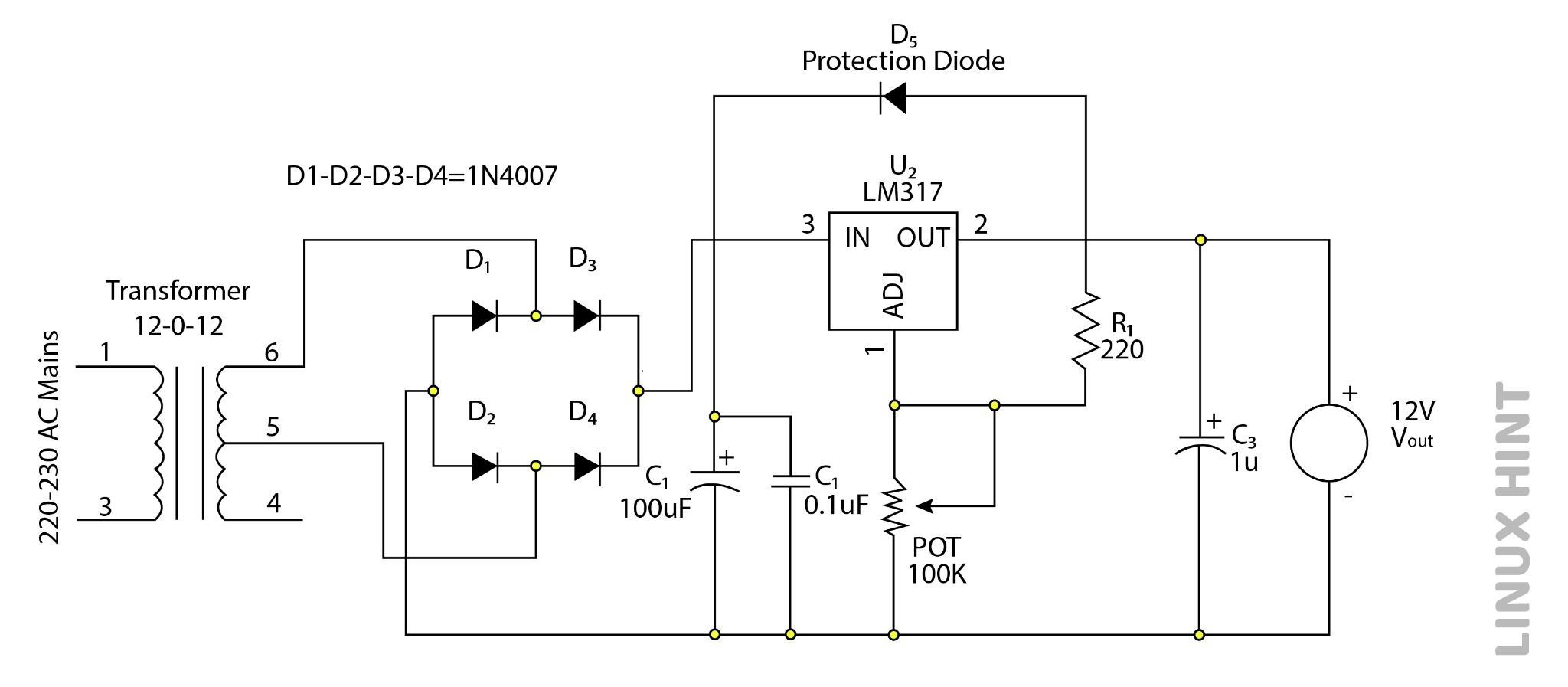
The 12-0-12 AC step-down transformer is used in this variable voltage power supply. A full-bridge rectifier is used to link the transformer’s center tape and end of the secondary coil. In the circuit diagram, the four 1N4007 diodes labeled D1, D2, D3, and D4 together form the full-bridge rectifier. D1’s cathode and D2‘s anode are linked to either end terminal, while D4’s cathode and D3’s anode is connected to the secondary coil’s center tap. The anodes of the diodes (D1 and D4) are linked from which an external terminal is pulled out for output from the full-wave type rectifier, and the cathodes of the diodes (D2 and D3) are connected.
Between the full-wave type rectifier’s output terminals is a 0.1 uF ceramic capacitor. An LM317 voltage regulator is attached in parallel to the capacitor for voltage control. A 1 uF/50V capacitor is connected in parallel to the output to compensate for transient currents, and a 10 K variable resistor is linked in a voltage divider configuration with the regulator IC to regulate voltage. For short circuit protection, a protective diode is attached between the voltage regulator IC’s input and output terminals.
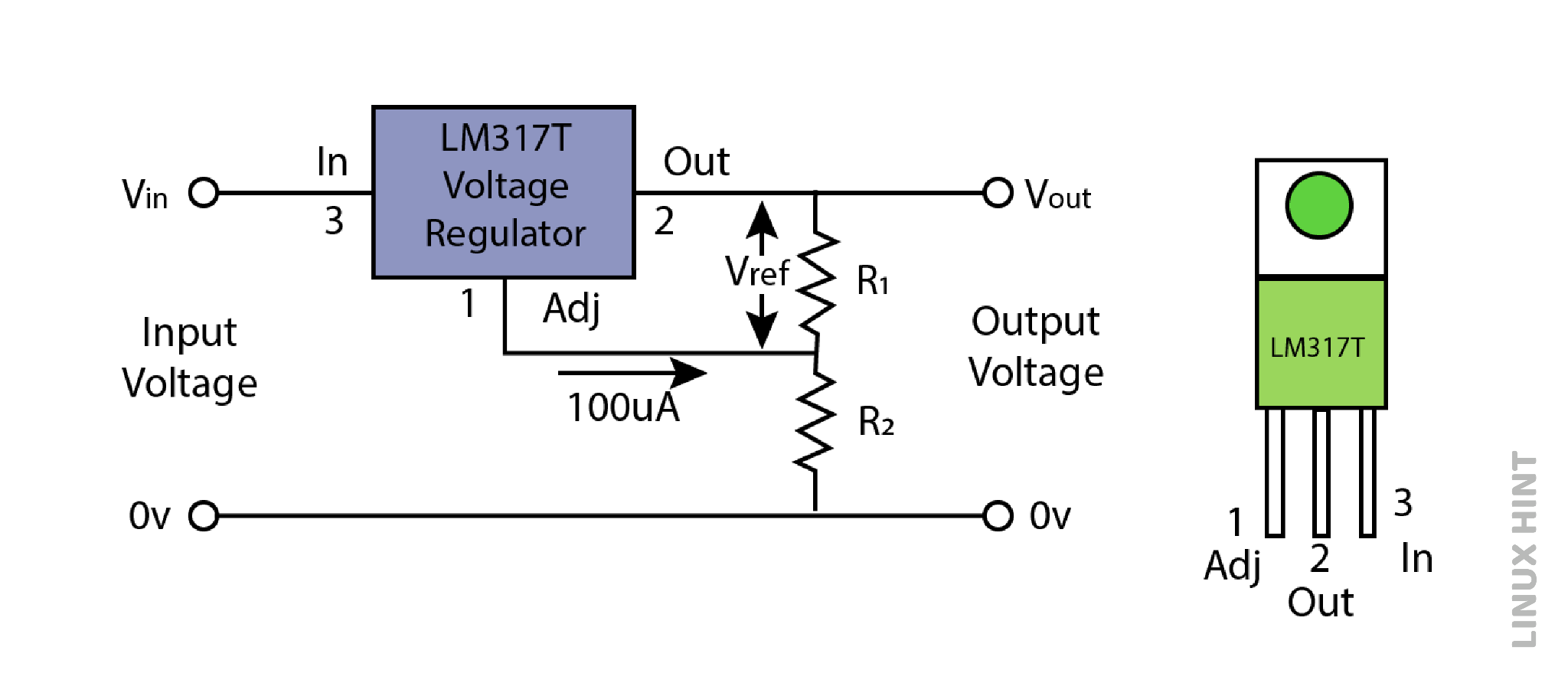
LM317 IC includes three pins: a. an input pin that can receive a supply of up to 40 V DC; b. an output pin that drives output voltage between 1.25 V and 37 V DC; and c. an adjust pin that allows for adjustment of the output voltage in coordination with the input voltage. The output ranges from 1.25 V to 37 V DC for inputs up to 40 V.
Operating Principle
The primary power source of this adjustable voltage power supply runs at a voltage of 220V–230V AC, which has to be further stepped down to 12V. A step-down transformer is used to convert 220V to 12V AC. The stepped-down AC voltage must be changed to DC voltage which is done through rectifiers. A full wave-based bridge rectifier is utilized in this voltage power supply circuit to convert 12V AC into output of 12V DC. Four diodes (1N4007) are coupled in a full-wave bridge rectifier such that electricity can only pass through them in one direction. The two of the diodes become forward biased during full-wave rectification, while two more diodes become reverse biased.
While diode D1 and diode D3 are in reverse bias during the positive half, diode D2 and diode D4 are forward biased. Current flows through the output terminals of D2 and D4 accordingly. Diodes D1 and D3 are biased forward during the negative half-cycle, while diodes D4 and D2 are reverse biased. Current passes through D1 and D3 at this time. Both of the present routes follow the same direction.
A capacitor is used to filter a DC signal during this operation. The full-wave rectifier’s output is not purely DC voltage. This will be combined with ripples. As a result, it must be filtered by coupling a capacitor in parallel configuration to the full-wave rectifier’s output.
The output of the rectifier circuit is linked to a capacitor with a value of 100 uF/25V. All of the AC that passes through this capacitor is sent to the ground in its capacity as a filtering capacitor. The remaining mean DC voltage is filtered and ripple-free at the output. The AC signal is filtered by a 0.1 uF capacitor.
A resistive voltage divider is utilized between the output pin of LM317 IC and the ground in this adjustable voltage power supply to establish the required voltage at the LM317’s output. The resistive voltage divider has a value of 100 K, which enables it to provide the needed voltage range at the output. This adjustable voltage power supply circuit may get the required voltage by altering the potentiometer.
A 1.25V constant reference voltage is supplied across the adjustment pin by the LM317. A 10 mA minimum load current is offered by the LM317.
Significance of Zener diode in Supply Circuit
A common component for driving the voltage across circuit is the Zener diode, which also serves as a voltage reference and shunt regulator. Under a variety of load current situations, it may be utilized to provide a stable voltage output with low ripples.
Conclusion
Numerous power source applications may make use of this adjustable voltage power supply circuit using voltage regulator IC LM317, It is used to drive the necessary voltage for different devices while also providing protection functions against device damages.