Control LED with a potentiometer is a basic level project that is used to change the brightness of LED according to the changing resistance of the potentiometer. This project is an example of a beginner-level project which is designed for making the understanding usage of Arduino.
We can fade the LED by changing its brightness. In this write-up, the circuit of controlling the LEDs with a potentiometer is discussed in detail.
How to control LED with a potentiometer
The potentiometer is also commonly known as a variable resistor, it is connected to a circuit to vary the voltage by increasing or decreasing the resistance. We will use this varying resistance to control the brightness of the LED like if we increase the resistance less current will reach the LED and it will glow less bright. Similarly, if we decrease the resistance, more current will be delivered to the LED and it will glow brighter.
We will make a circuit in which we will control the brightness of LED by varying the resistance of a potentiometer and the components required for this circuit are:
- Arduino Uno
- Potentiometer of 1k ohm
- LED
- Breadboard
- Connecting wires
We will consider the Arduino code for control LED using a potentiometer:
pinMode(ledpin, OUTPUT);
}
void loop(){
potvalue = analogRead(potpin);
bright = potvalue/10;
analogWrite(ledpin, bright);
}
Explanation of code: In the above code, we declare four integer variables ledpin, potpin, potvalue, and bright; in ledpin, we stored 11 which will be the pin number where LED will be connected and stored A1 in potpin, which is the analog pin from where potentiometer will read the input. Then using the pinMode() function we have declared the ledpin to behave as an output. Then in the loop section, we take the input from potpin and store the results in potvalue, then divide this value by 4 (to keep it in the range of 0 to 255) and store the results in a bright variable. Then using the bright variable’s value, we glow the ledpin.
Hardware and simulation of the circuit:
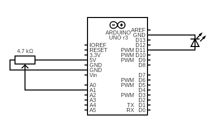
The circuit diagram of the circuit of “Control LED with potentiometer” will be:
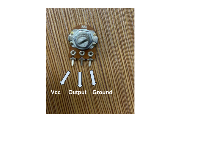
Explanation of the circuit: The cathode of LED is connected to the ground and the anode of LED is connected with the pin D11 of Arduino Uno. The potentiometer has three legs; one leg is connected to 5 volts, one is connected to the ground, and the middle pin is connected to A1.
The simulation of the circuit is:
It can be seen from the above, by varying the value of the potentiometer, the brightness of the LED is changing.
The hardware configuration of the above circuit is:
Conclusion
The brightness of the LED can be controlled with the help of a potentiometer commonly known as the variable resistor. We manually set the voltage across the LED by varying the resistance which also varies the brightness of a LED. In this write-up, the circuit of controlling the brightness of a LED with a potentiometer has been explained along with its circuit diagram and hardware configuration.


