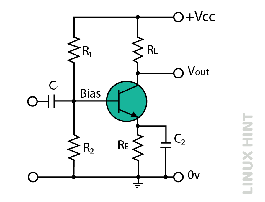
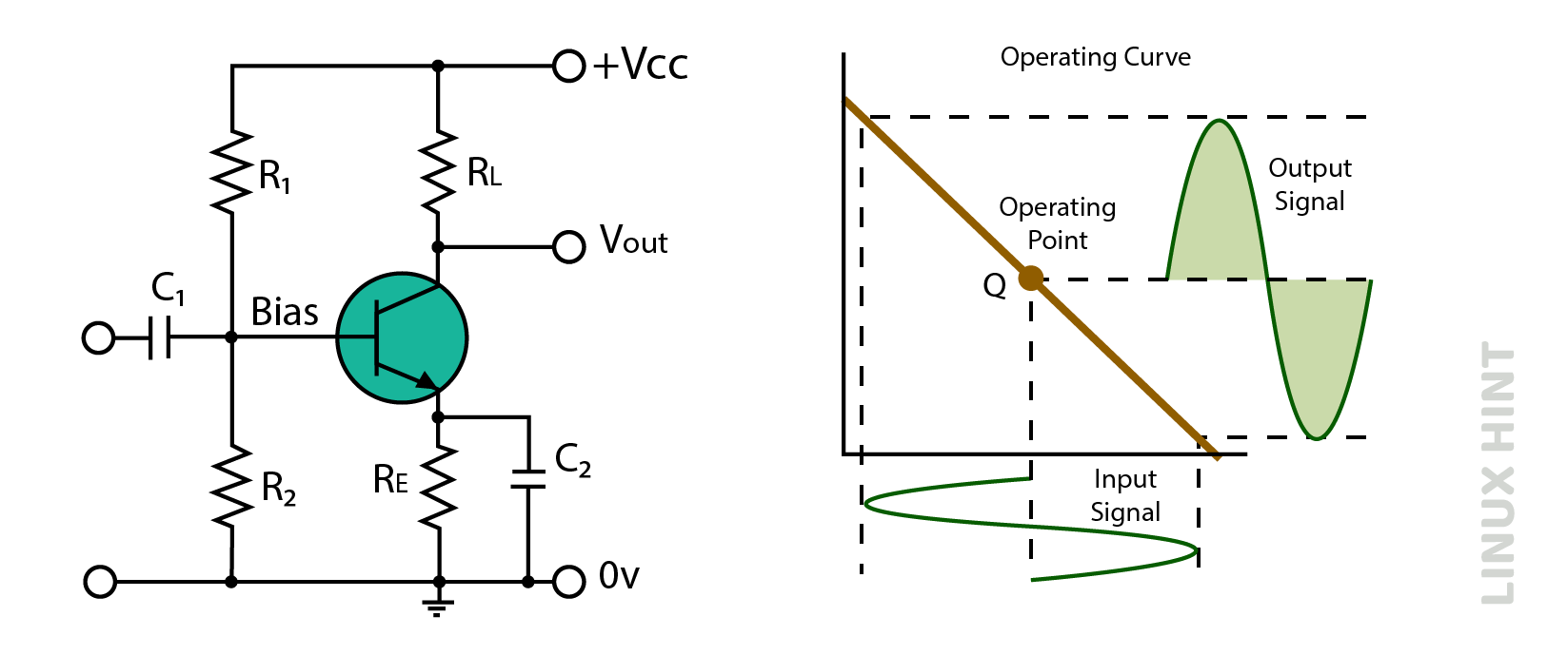
Power amplifiers are categorized according to how they operate, specifically according to the segment and duration of conduction of the input cycle. Power amplifiers are categorized into Class A, AB, C, D and E. This article will provide a comprehensive analysis of Class A amplifiers.
Class A Amplifier
Class A power amplifier conducts current continuously throughout the entire cycle of the input signal. Because of its low efficiency, this amplifier class is less often used in higher power stages.
Working Principle of Class A Amplifier
The main purpose of class A amplifiers is to minimize the presence of noise by ensuring that the signal waveform remains within the non-linear region of the transistor’s input characteristic, namely between 0V and 0.6V. The basic arrangement of class A amplifier is given below:
In class A amplifiers, a significant portion of the power generated by the amplifier is dissipated as heat, resulting in waste. The main reason for the low efficiency of class A amplifiers is the continuous biasing of the transistors, which results in a small current flow even in the absence of an input signal.
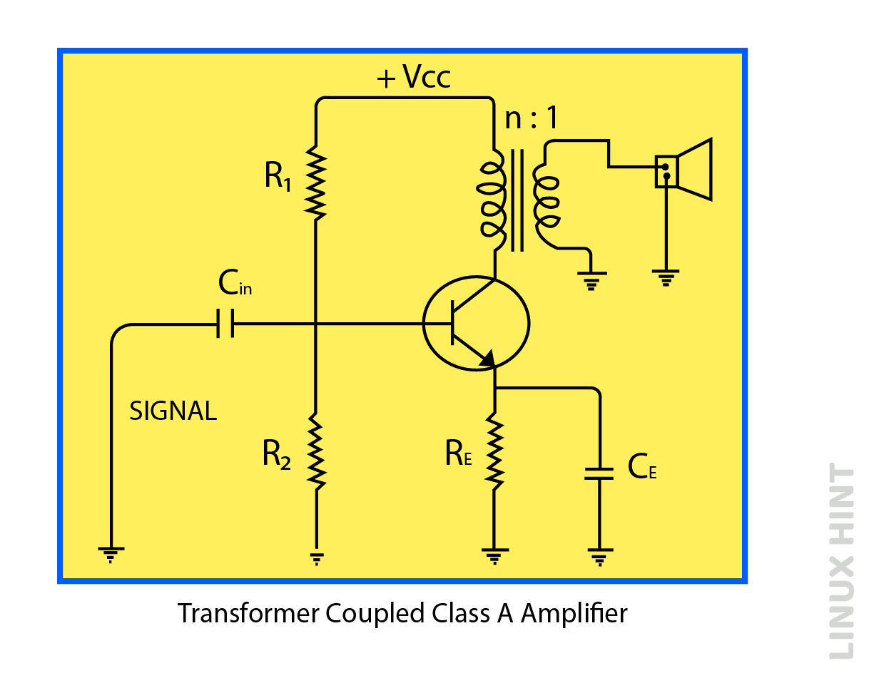
The class A amplifiers can also be directly coupled. A direct-coupled class A amplifier connects load to the output of the transistor by using a transformer. A coupling transformer facilitates effective impedance matching between load and output, thus serving as a major contributor to increased efficiency.
The circuit comprises voltage divider resistors R1 and R2, as well as a bias resistor and an emitter Re, which serve to stabilize the circuit. A bypass capacitor CE and the resistor Re are connected in parallel at the emitter to reduce the transient effects. The input capacitor, also known as the coupling capacitor (Cin), serves to couple the AC voltage of the input signal to the base of the transistor while preventing DC current from the previous stage from passing through.
In principle, current flow is through the resistive load of the collector, resulting in a direct current dissipation in it. Therefore, direct current (DC) power is transformed into heat energy inside the load without generating alternating current (AC) power output. However, it is not recommended to directly transfer the electrical current through the output device. Therefore, to achieve this goal, a specific configuration is applied by using a suitable transformer to establish a connection between the load and the amplifier, as seen in the above-mentioned diagram.
Impedance Matching
The process of achieving impedance matching involves changing the output impedance of the amplifier in a manner such as to match its input impedance.
Impedance matching can be achieved by carefully selecting the number of turns in the main winding to ensure that its total impedance matches that of the output impedance of the transistor. Similarly, the number of turns in the secondary winding must be chosen to create a net impedance that matches the input impedance as well.
Output Characteristics
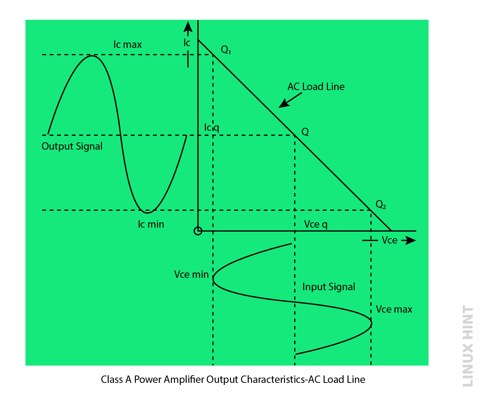
Based on the below diagram, it is evident that the Q-point is precisely positioned at the midpoint of the AC load line and the transistor remains conductive throughout the input waveform. The maximum efficiency is 50% in class-A amplifiers.
In practical applications, system efficiency can be significantly reduced, potentially as much as 25%, due to factors such as capacitive coupling and the presence of inductive loads such as loudspeakers. In other words, almost 75% of the power is wasted within the amplifier. A significant portion of the power dissipation occurs as heat inside the active components, especially the transistors.
Conclusion
Class A amplifiers amplify and conduct the complete input signal at output. They operate without any interruptions and have a very simple configuration. However, due to continuous operation, they are prone to power loss and require heat sinks to mitigate heating effects.


