Capacitors store energy between their plates. These plates are conductive in nature and store energy in the form of electrical charge. Capacitor stored charge depends on the material used between two plates of the capacitor. This material is also known as dielectric. Capacitors come in various types based on the material they’re made from. These range from paper capacitors to mica capacitors.
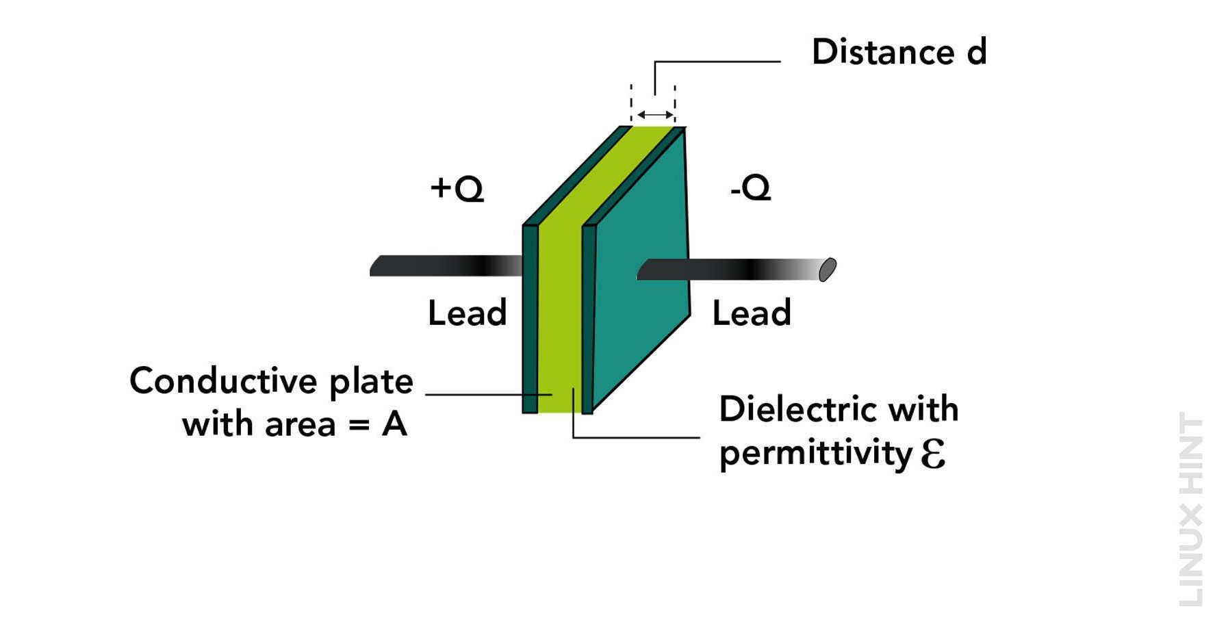
Capacitors do not behave like resistors. As in resistors, there is a continuous flow of electricity depending upon the source voltage connected. A capacitor operates by charging and discharging. The total flow of electricity across any capacitor depends on the voltage change rate connected across it. This resistance to voltage change must not be confused with reactance, as the reactance is completely different from capacitance.
When electricity passes through a conductor, it generates a magnetic field around it. This affects the opposition to the current, which is called inductive reactance.
Similarly, a capacitor is made of two conductors that have an insulator between them. This capacitor stores and releases electric charge. This results in changing the electric field between the conductors. This also impacts the resistance to the flow of current, known as capacitive reactance.
Quick Outline:
- What is Capacitance in an AC Circuit
- Sinusoidal Waveforms for AC Capacitance
- Phasor Diagram for AC Capacitance
- Capacitive Reactance in AC Circuit
- Capacitors in Low Pass Filters
- Capacitors in High Pass Filters
- Example 1
- Example 2
- Example 3
- Conclusion
What is Capacitance in an AC Circuit
When you connect a capacitor across the constant DC supply, it begins to charge. The capacitor charges until it reaches the same value as the applied potential across its terminals. This charge will remain on capacitor plates as long as the voltage is present. Once the voltage starts getting decreased, the capacitor will begin to discharge. A pure or ideal capacitor can maintain this charge even if the applied DC voltage is removed.
AC Capacitance is the charge-storing capacity of any capacitor in an AC circuit. In the case of an AC circuit where there is a sinusoidal wave, the capacitor will keep on charging and discharging. The charging and discharging rate is determined by the frequency of the AC supply voltage.
An AC capacitor has two plates that can store electric charge when a sinusoidal voltage is applied across them. The voltage changes its polarity periodically, making the capacitor charge and discharge in both directions. However, the capacitor cannot adjust to the voltage changes instantly. Because it takes time to transfer (or remove) the charge from the plates. It means that the voltage across the capacitor lags behind the applied voltage by a specific amount of time. This delay is given by:
Sinusoidal Waveforms for AC Capacitance
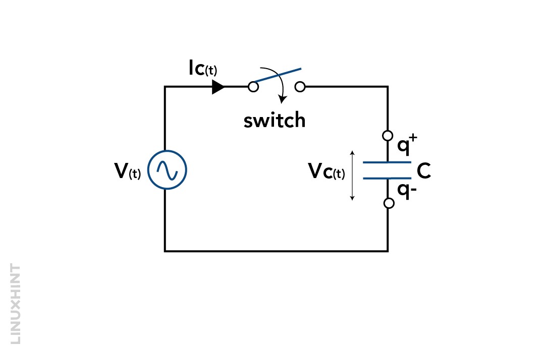
To understand the working of a capacitor with an AC supply, we can consider an AC circuit with a capacitor in it. The below diagram represents a sinusoidal supply circuit with a capacitor connected:
OCT
The circuit above has a switch and a capacitor. Initially, when the switch is turned on, there is no charge on the capacitor. A large current flows into it from the sinusoidal voltage source (V). The voltage source changes its value and direction in a regular pattern.
From 0° to 90°:
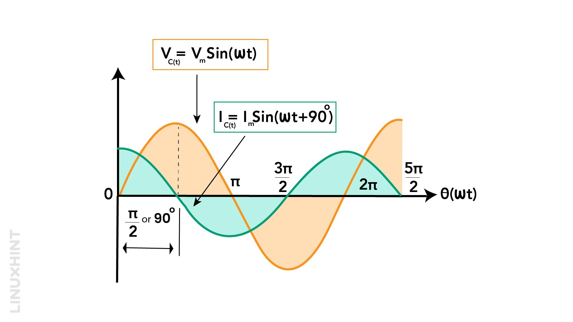
The value of V is increasing at its highest positive rate of change as it crosses the zero point at 0°. This means that the capacitor gets the most current at this time because the most electrons are moving from one plate to another to match the change.
As the AC sinusoidal waves reach the 90° point, the charging of the capacitor stops. As of now, the capacitor is not charging or discharging. The total current drops to zero because there is no more change in voltage.
From 90° to 180°:
Then the voltage source starts to go down toward the zero point at 180°. The capacitor still has a positive voltage, so it releases some of its electrons on its plates to keep the voltage constant.
This will result in the flow of current in the negative or opposite direction. When the voltage source crosses the zero point at 180°, it changes its value and direction at the fastest rate. The capacitor also gets the most current at this time, because it tries to match the voltage change by moving electrons between its plates. The voltage across the plates is zero at this point because both plates have the same amount of charge.
In this first half cycle from 0° to 180°, the current reaches its maximum possible value before the voltage does by a quarter (1/4f) of the cycle. This means that the voltage in a purely capacitive circuit is behind the current by 90°.
The circuit has a capacitor and a sinusoidal voltage source V. The voltage source changes its value and direction in a regular pattern.
From 180° to 360°:
In the second half cycle from 180° to 360°, the voltage source goes in the opposite direction and reaches its lowest negative value at 270°. The capacitor voltage is the same as the source, but it cannot change it instantly. The current stops flowing into the capacitor at this point. Now the capacitor is charged but in the opposite direction. Then the voltage source starts to go upwards towards the zero point at 360°.
The capacitor still has a negative voltage, so it releases some of its electrons on its plates to keep the voltage constant. This will result in the opposite flow of current or towards the positive direction. When the voltage source crosses the zero point at 360°, the cycle repeats itself.
The current and the voltage in the circuit are not in sync, because of the capacitors charging and discharging behavior. The current always leads the voltage by 90° or a quarter of a cycle. This phenomenon is opposite to the AC inductance circuit.
We can also show the effect with a phasor diagram, where the voltage is behind the current by 90°. But we can also say that the current is ahead of the voltage by 90° if we use the voltage as our reference.
Phasor Diagram for AC Capacitance
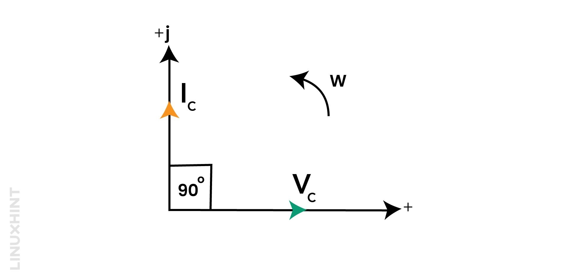
A phasor diagram is a visual representation of the magnitude and direction of an alternating quantity, such as voltage or current. In a pure AC capacitance circuit, the capacitor charges and discharges alternatively at the same frequency as the supply voltage. For capacitors, the current leads the voltage by 90°.
The phasor diagram of AC capacitance shows the current and voltage as two vectors that are perpendicular to each other. The current vector points upward and the voltage vector points to the right. The length of each vector represents the peak value of the corresponding quantity. The angle of the two vectors is called the phase angle. This angle indicates the current lead over the voltage.
In pure capacitor voltage, Vc lags the current Ic by 90°, or in other words, you can say that the Current Ic leads the Voltage Vc by 90°. The following image illustrates the phasor diagram for a pure (ideal) capacitor in an AC circuit. The phasor diagram of AC capacitance can help you understand the relationship between the current and voltage waveforms, as well as the power dissipation in the circuit.
Capacitive Reactance in AC Circuit
In AC circuits, capacitive reactance is the term used to describe how a capacitor opposes the flow of current. It is similar to resistance, but it is not the same. Both resistance and reactance are measured in ohm. But the difference is in their symbol. Capacitive reactance is denoted by the symbol X. For AC circuit capacitance, we use the symbol Xc.
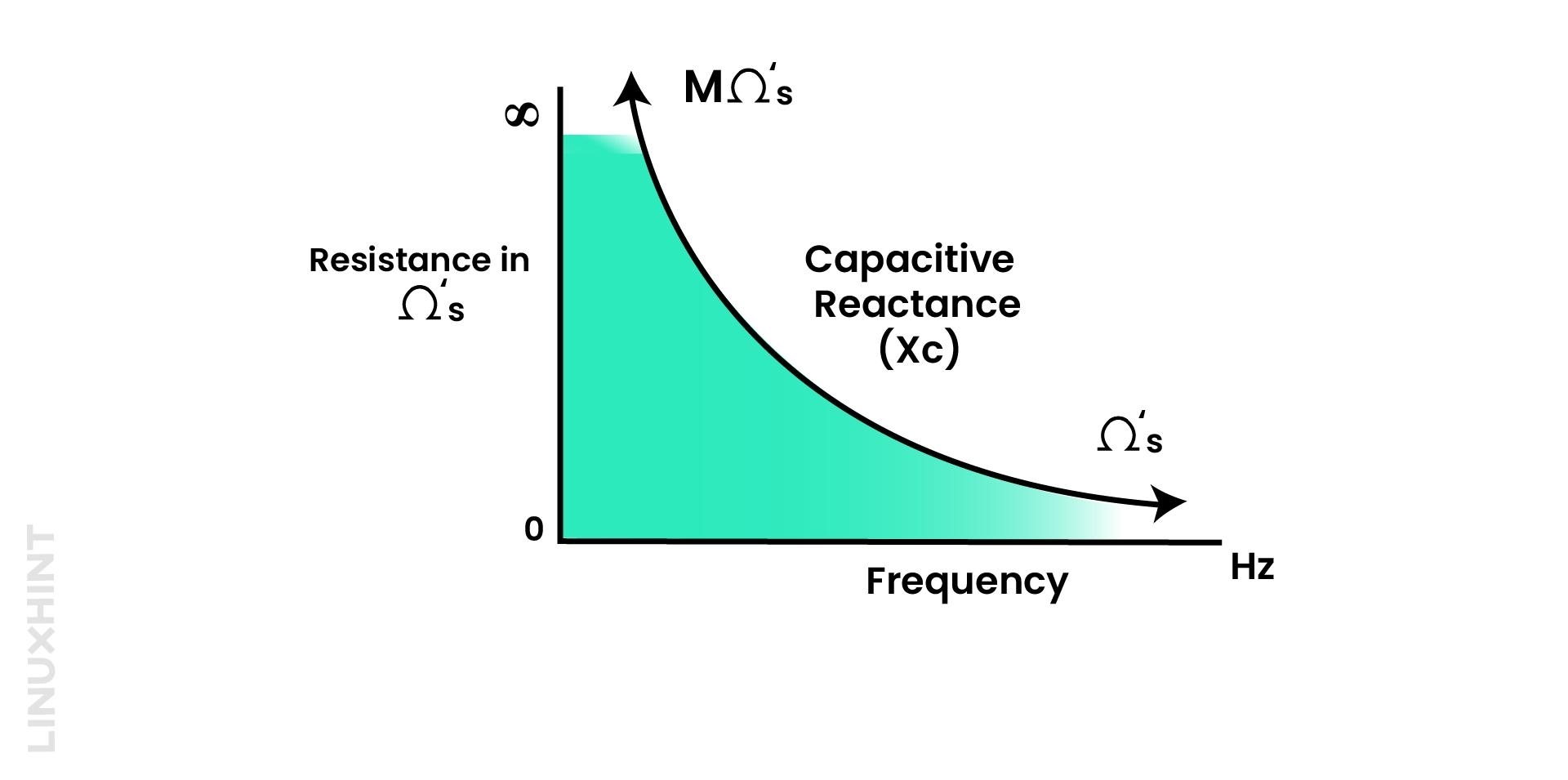
Reactance is a mutual quantity that applies to both inductors and capacitors. For capacitors, we call it Capacitive Reactance. Capacitive reactance changes with the AC input frequency and the capacitor capacitance. Capacitive reactance decreases with an increase in AC input frequency. Capacitive reactance is given by:
From the given formula, it can be concluded that either the term frequency or capacitance increases results in the decrease of the Capacitive reactance.
Capacitive reactance is inversely related to the frequency of the AC waveform. As the frequency decreases or approaches zero (DC), the capacitive reactance of the system increases by manifolds. This will result in a very high resistance value.
Capacitors in Low-Pass Filters
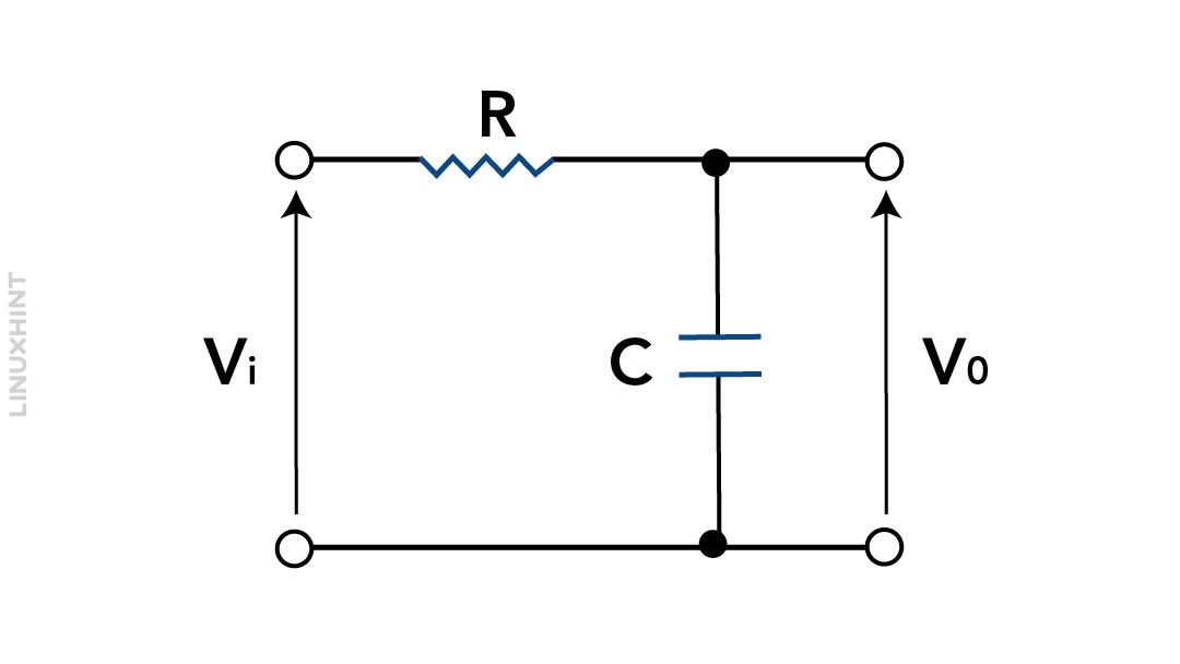
A low-pass filter is an electrical circuit that allows frequencies below a specific cut-off frequency to go through while preventing higher frequencies from passing.
In a low-pass filter, there is a resistor connected in series with the input signal, and a capacitor is linked in parallel with the output signal. The output voltage is measured across the ends of the capacitor. For low frequencies, the capacitor behaves like an open circuit, so the output voltage is nearly the same as the input voltage.
A low pass RC filter cut-off equation is given by:
For higher frequencies, the capacitor functions as a short circuit, causing the output voltage to be nearly zero. The cut-off frequency of a low-pass filter is the frequency at which the output voltage is reduced to half of the input voltage. This cut-off frequency depends on resistor and capacitor values.
Capacitors in High-Pass Filters
A high-pass filter is an electrical circuit in which only frequencies higher than a certain limit can pass through a high-pass filter. It blocks the lower frequencies.
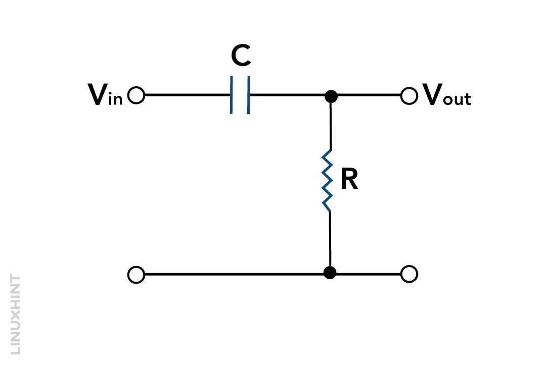
In a high-pass filter, a capacitor is connected in series with the input signal, and there is a resistor in parallel with the output signal. The output voltage is taken across the resistor. For higher frequencies, the capacitor behaves like a short circuit, resulting in the output voltage being nearly the same as the input voltage. The capacitor acts as an open circuit for low frequencies, so the output voltage is almost zero.
A high-pass filter cut-off frequency is:
The cut-off frequency of a high-pass filter is where the output voltage reaches half of the input voltage. This frequency is determined by the values of both the resistor and the capacitor.
Example 1
A capacitor with a capacitance of 102/π microfarads (μF) is connected to a 220-volt, 50-hertz (Hz) alternating current (AC) mains supply. Calculate capacitive reactance and RMS value of the current. Also, write voltage and current equations.
Solution:
Given data:
(i) Capacitive reactance can be given by:
Putting the given value in the formula:
(ii) RMS value of current:
(iii) Voltage and Current relation:
To find the voltage and current, first convert their respective RMS values to instantaneous values.
Voltage Equation:
Current Equation:
Example 2
What is the capacitive reactance and peak current through a 0.5 μF capacitor with an AC voltage of 16sin(2×10³t)?
Solution:
Capacitance = C = 0.5 µF = 0.5×10⁻⁶ F, V = 16sin(2×10³ t)
Capacitance Inductance, Xc =? Im =?
Capacitive inductance can be given by the following equation:
For the capacitor, the instantaneous voltage V is given by:
Now compare the instantaneous voltage equation with the given equation. We will have the following results:
Put all these data in equation A, we will get the value of Xc:
Similarly, for peak current, use the following equations:
Now put the values:
Example 3
In a series circuit, a 30 Ω resistor and a 79.5 µF capacitor are connected to a power supply with a voltage of 100 V and a frequency of 50 Hz. Determine the following:
(a) The circuit’s impedance.
(b) The current flows through the circuit.
(c) The angle by which the voltage and current are out of phase.
(d) The equation describes the current at any given moment in the circuit.
Solution:
(a) The impedance of a series RC circuit is given by:
Here, the R is resistance and Xc is capacitive reactance. The capacitive reactance is given by:
In the above equation, f is the frequency (Hz) and C is the capacitance (F). Now substitute values:
Now, we can calculate the impedance:
(b) The current in the circuit according to Ohm’s law:
where:
I represent the current in amperes
V stands for the voltage in volts
Z represents the impedance in ohms
Substituting the values given in the problem, we get:
Therefore, the current in the circuit is 2 amperes.
(c) The phase angle between the voltage and current in a series RC circuit is given by:
Substituting the values given in the problem, we get:
Therefore, the voltage and current phase angle is 53°. Here, the current is leading the voltage by 53°.
(d) The equation for the instantaneous current in a series RC circuit is given by:
where:
I(t) is the instantaneous current in amperes
Im is the maximum current in amperes
ω denotes angular frequency (rad/s)
t is the time in seconds
φ is the phase angle in degrees
The maximum current is given by:
where:
IRMS is the effective current in amperes
Substituting the values calculated in parts (b) and (c), we get:
The angular frequency is given by:
Substituting the value of the frequency given in the problem, we get:
Now, we can substitute all the values into the equation for the instantaneous current:
This is the required equation for the instantaneous current in the circuit.
Conclusion
Capacitors store electrical energy when connected with alternating current (AC) sources. AC capacitance is determined by the size and spacing of the capacitor’s plates. It also depends on the dielectric material used between capacitor plates. When an AC voltage is applied to a capacitor, it charges and discharges at a rate determined by the frequency of the AC voltage. The higher the frequency, the faster the capacitor charges and discharges, and the lower the AC capacitance.
The effect of AC capacitance in a circuit is to create a capacitive reactance, which opposes the flow of current. Capacitive reactance is inversely related to the frequency of the AC voltage. This means that as the frequency goes up, the capacitive reactance decreases.


