What is an RC Oscillator?
An RC oscillator uses linear electrical components to create a sine wave. At high frequencies, the oscillators work like tuned LC circuits, but at low frequencies, the capacitors and inductors in the electrical circuit would be quite large. This oscillator is preferable for low frequency-based applications. RC oscillator comprises an amplifier along with a feedback circuit. The feedback known as phase shift can be created using resistors and capacitors.
Working Principle
The RC oscillator circuit uses the RC network to provide the phase shift of the response signal it needs. These oscillators produce a clean sine wave for a wide variety of loads and have a high frequency.
The basic RC oscillator using a transistor is shown below. The transistor in this circuit is an active element of the amplification stage. The supply voltage Vcc and resistors R1, R2, RC and RE define the DC operating point of the active region of the transistor.
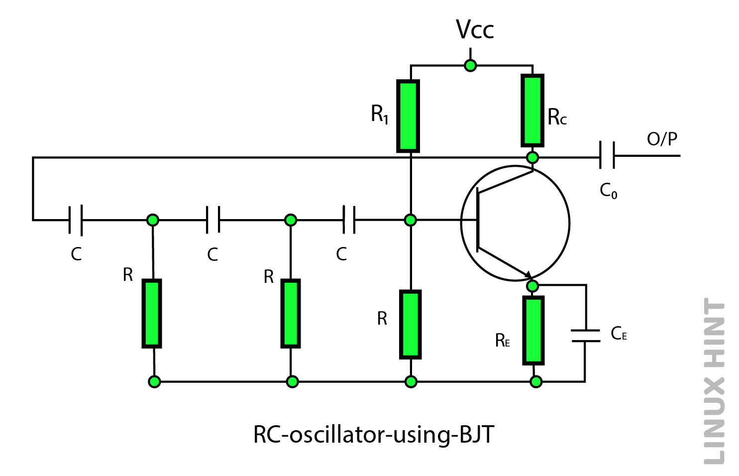
CE in the above circuit acts as a bypass capacitor. Here the three of the RC segments are equivalent and R’ = R – hie represents the final resistance of the section. The ‘hie’ represents resistance of the transistor’, so the overall network resistance of the circuit is ‘R’.
R1 and R2 resistors do not affect the circuit operation. The minimum value of impedance available from the RE-CE combination also has minimal effect on the AC operation.
The noise voltage causes the circuit to oscillate when power is applied. An amplifier with a small base current creates 180-degree phase shift currents in the transistor amplifier. This signal will be phase shifted 180 degrees again when it responds to the inputs of the amplifier. For unity gain, the oscillations will continue.
Using an analog AC circuit simplifies the circuit and gives the oscillation frequency:

If Rc/R <<1;

From the above equations, changing the capacitor and resistor values changes the oscillation frequency.
RC Oscillator with Operational Amplifier
The figure below shows an oscillator with an operational amplifier and three of the RC cascaded circuits used as feedback circuits.
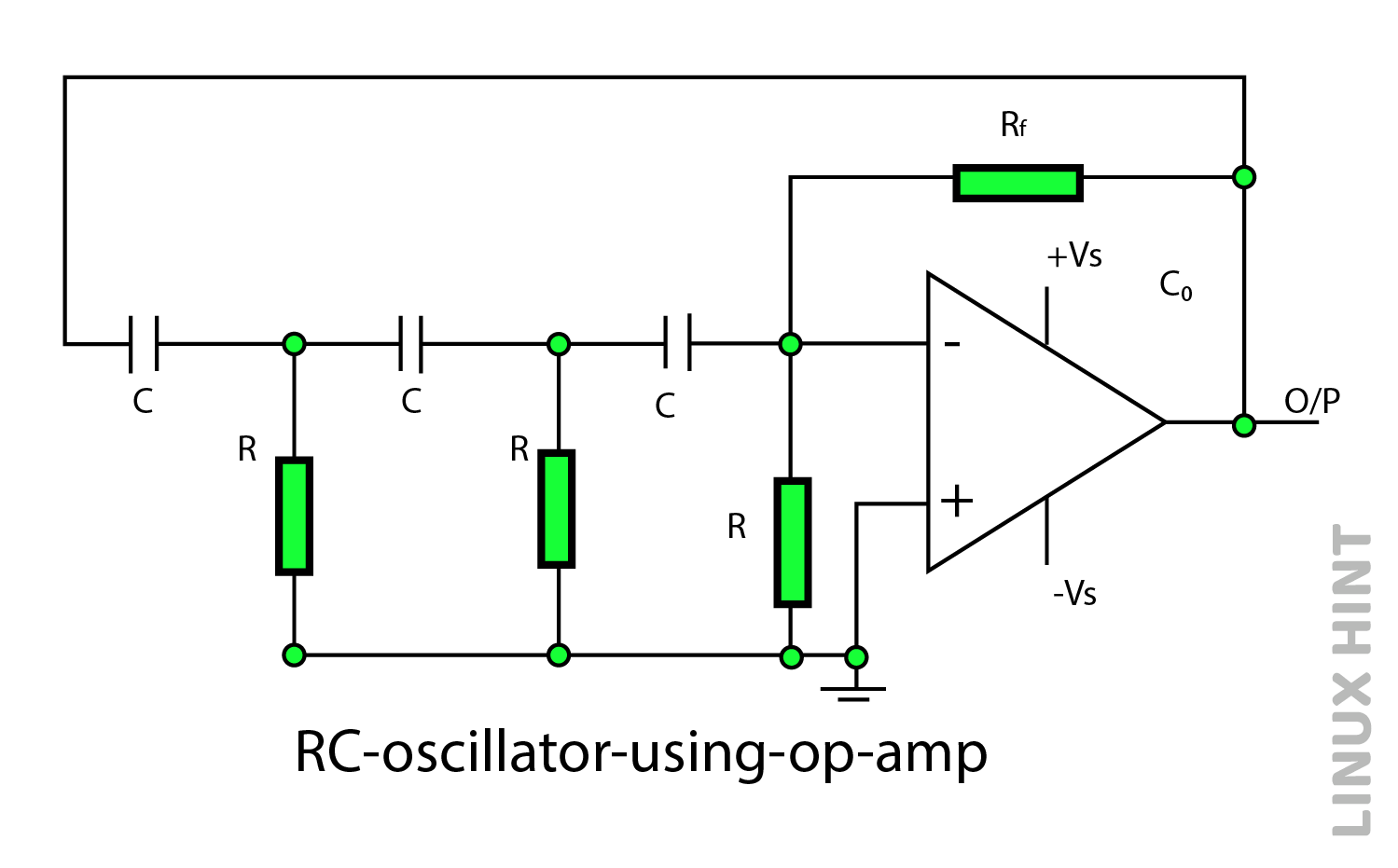
Since this op-amp is inverting, its output signal is 180 degrees from the input signal at the inverting terminal. The RC feedback network adds 180 degrees of phase shift, causing oscillations.
Resistors such as Rf and R1 can adjust the gain of an operational amplifier. Adjust the gain so that the gain of the feedback network and the gain of the op-amp are slightly greater than 1 to achieve the desired oscillations.
A circuit gain greater than 1 makes that circuit an oscillator if the op amp has a gain greater than 29. The oscillation frequency can be obtained using the following equation:
The oscillation condition can be ensured with A ≥ 29. The amplifier gain can be adjusted so that the oscillations occur within the circuit controlling R1 and Rf.
How to Build an RC Oscillator Circuit?
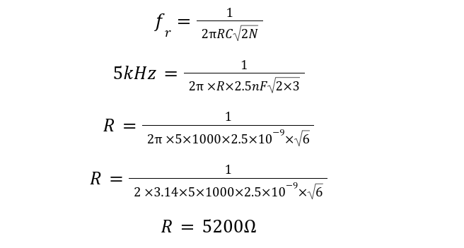
For the oscillatory frequency of 5kHz, design a three-stage RC oscillator circuit with feedback capacitors of 2.5nF. Draw the final RC oscillator. The frequency output of RC oscillator is given by:
For calculating feedback resistor in op-amp configuration:

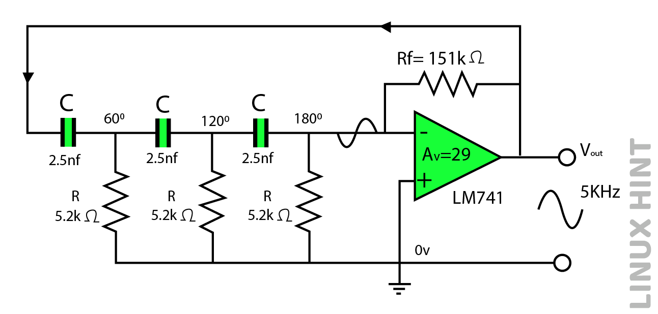
The standard op-amp gain to sustain oscillations is 29:


RC Oscillator Circuit shall be as follows:
Conclusion
In RC oscillators, the frequency can be changed using capacitors or resistors. However, resistors are kept fixed while the capacitors are adjusted as per requirements. They are used as oscillators for musical instruments, audio frequency generators and synchronous receivers.