The attenuators are used to lower the signal strength without affecting the signal quality moreover, the signal could be a voltage, current, or any data signal. In circuits, attenuators are used to lower the voltage for better impedance matching. However, while measuring signals, attenuators are used to lower the signal strength so that it might not damage the measuring device.
Outline:
- What is an Attenuator
- Construction and Working of an Attenuator
- Types of Attenuators
- L-pad Attenuator
- L-pad Attenuator with Equal Impedance
- L-pad Attenuator with Unequal Impedance
- T-pad Attenuator
- T-pad Attenuator with Equal Impedance
- T-pad Attenuator with Unequal Impedance
- Bridged-T Attenuator
- Variable Bridge Attenuator
- Pi-pad Attenuator
- Pi-pad Attenuator with Equal Impedance
- Pi-pad Attenuator with Unequal Impedance
- Conclusion
What is an Attenuator
When a signal is transferred from one point to another, it loses some of its strength, which is referred to as attenuation. However, this phenomenon is useful for many other applications like test equipment, impedance matching, and balancing the signal levels. Natural attenuation results in losses in the quality of the signal, however using the attenuators to attenuate any signal preserves the quality of the signal. An attenuator generally consists of resistors connected in different configurations, which results in different types of attenuators.
Construction and Working of an Attenuator
An attenuator is a four-terminal two-port device that consists of a resistor network that produces a distortion less output signal with no phase shift. A typical attenuator is a resistive voltage divider circuit that reduces the gain, unlike amplifiers. For instance, if there is 1 volt on the input of the attenuator and at the output it is reduced to 1 mV then it means that there is a reduction of 1000th. To simply calculator the attenuation ratio, the output is divided by the input, and it will be unit less:
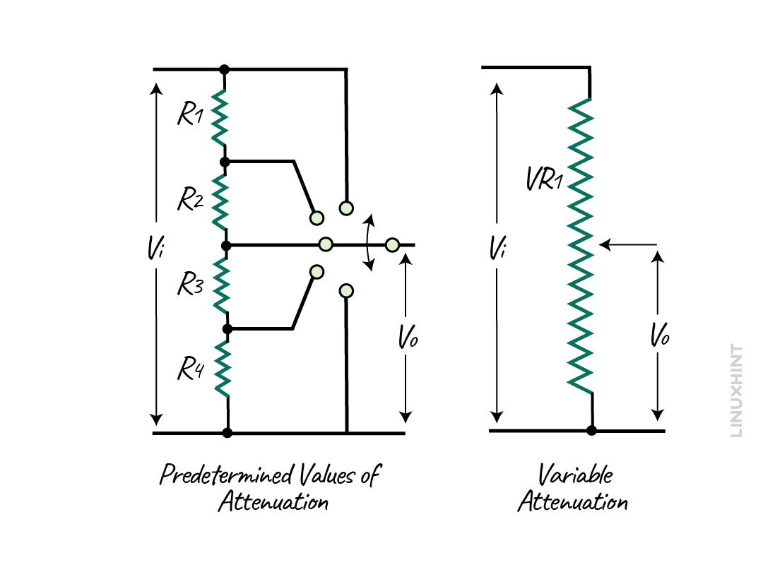
An attenuator can either be fixed by having predetermined values that can be selected through a dial, or it can be a variable in which desired values can be set. The attenuator network usually ranges from 1dB to 20dB.
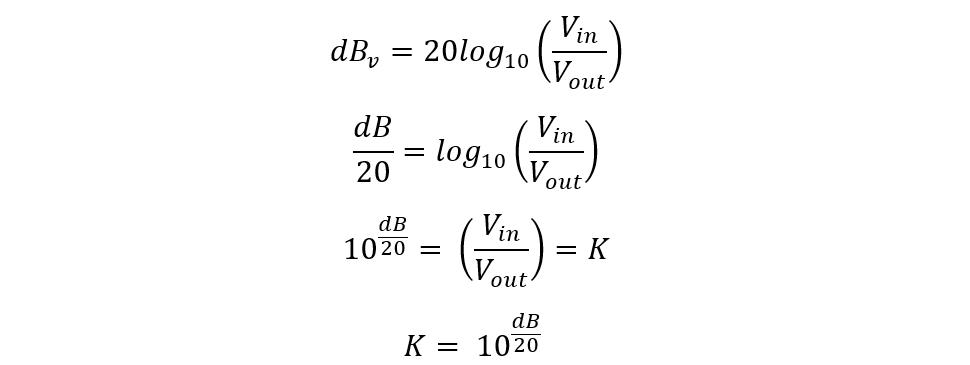
The performance of the attenuator is usually measured in decibels, that is, the decrease in the input signal per frequency decade or octave. Since the 10 decibels is equal to the one Bel, the ratio between the input and output signal is given as:
The decibel is a logarithmic ratio having no physical units so in the passive attenuators it is always the best way to assign a reference value of zero and then compare the output with it. So, for instance, if the attenuation of any signal is -6dB then it means that the value is 6 dB below zero. Further, to find out power attenuation the following equation can be used:
Example 1: Calculating the Power Attenuation
Consider a circuit whose input power is 20 watts, and, on the output, it gives the 10 watts what would be the power attenuation:
Now here the power attenuation is 3 decibels.
Example 2: Calculate the Power Output
The power of a cable having a length of 25 KM is 500 mW and the attenuation per unit length of cable is 2dB/KM. Calculate the output power of the signal from the cable.
As mentioned above, the equation for calculating the attenuation is given below:
Since the attenuation rate per kilometer is given, then the attenuation for the 25 KM line will be:
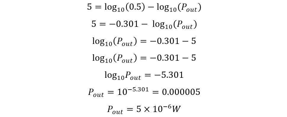
Now placing the values in the equation for power attenuation, we get:
Now using the following log property:
Now the equation will be:
So, on the output will be 5×10⁻⁶ W.
Example 3: Calculating the Voltage Attenuation
Consider a circuit having an input voltage of 20mV and output voltage of 10mV, then what would be the attenuation of the voltage signal in decibels?
As mentioned above, the equation for calculating the attenuation is given below:
Now placing the values in the equation for power attenuation, we get:
Example 4: Calculating the Output Voltage
If the attenuation is 40 dB and the output voltage is 60mV, then find the input voltage using the voltage ratio equation:
Now placing the values in the equation for power attenuation, we get:
Now, taking anti-log on both sides of the equation:
So, the input voltage was 6 V which was attenuated to 60mV and the attenuation ratio was 40 decibels.
Types of Attenuators
Attenuators as mentioned above are pure resistive circuits and are classified into different types and can be arranged either into balanced or unbalanced states depending on the application. Further, here are some types of attenuators:
- L-pad Attenuator
- T-pad Attenuator
- Bridged-T Attenuator
- Pi-pad Attenuator
L-Pad Attenuator
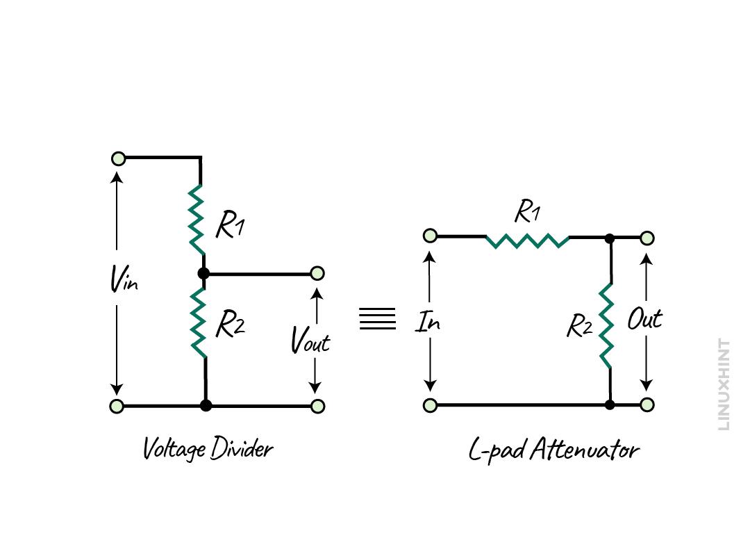
This is the basic type of attenuator, which is a voltage divider often used in electrical circuits for generating low voltage. Moreover, this type of attenuator configuration is used in circuits that are dependent on frequency. Like to create attenuation in the transmission line or to match the impedance for the unbalanced load and source.
Here the two resistors are connected across the input voltage, whereas at the output there is one resistor that is connected. Since both here R2 is in parallel, the output voltage will be:
Since this attenuator consists of pure resistive elements, there is no phase shift, and when this attenuator is connected across the source and load then the source voltage will be unchanged and remain the same. The L-pad attenuator can match the impedance in one direction only if the resistance values are constant and the impedance is finite. Moreover, if the source impedance is not similar to that of the load impedance, then it can only match either of the impedance instead of both.
L-pad Attenuator with Equal Impedance
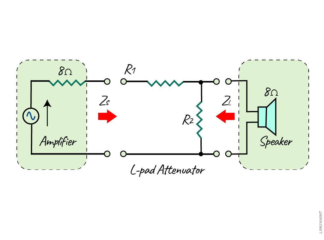
Consider an instance if the impedance source and the load are the same as if it’s 8 Ohms and the attenuation in decibels is 6 what would be the values of the R1 and R2? To make it simpler, consider the load as a speaker having a source impedance of 8 Ohms:
To calculate the resistance values, here are the equations for the sources side:
To further simplify the equation, we write k as the attenuation ratio, and for voltage it will be:
Now for the power ratio, the value of K will be:
Now the equations for finding the resistances will be:
Now calculating the values of K:
Now just place the values in the above equations and remember that here ZS is equal to ZL:
Now there is a problem with this type of configuration as the impedance matching is in the direction of resistor R1. This causes the mismatch of impedance towards the parallel resistor R2 and as a result, the mismatch will become larger as the attenuation increases. This can damage the circuitry of the speaker, so to fix such issue of overloading the source is by matching the impedance in the direction of the load.
In this case, the equations for finding the resistances will be slightly different:
Now putting the values in the above equations, we get:
Now from the above values it can be seen that if we increase the value of attenuation there will be a steady change in the impedance which is much safer for the circuit.
L-pad Attenuator with Unequal Impedance
If the source and load have unequal impedance, then this configuration will match the impedance either in the large or small impedance direction, but not on both. So, in the case of independence-matching in the direction of larger impedance, the equation for finding the resistances will be:
Now, the equations for finding the value of S:
Now if the impedance matching is in the direction of smaller impedance, then:
Example: For Unequal Impedance
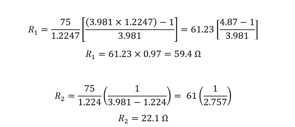
Consider a transmission line having an impedance of 75 Ohms, and it is connected to the signal strength meter having an impedance of 50 Ohms, and the maximum attenuation it can display is -12 dB. To match the impedance in the direction of the smaller impedance side using its respective equations:
Now put the values in the equations for finding the resistance values:
Here, from the above calculation, it can be seen that the values for resistance are near to the preferred values.
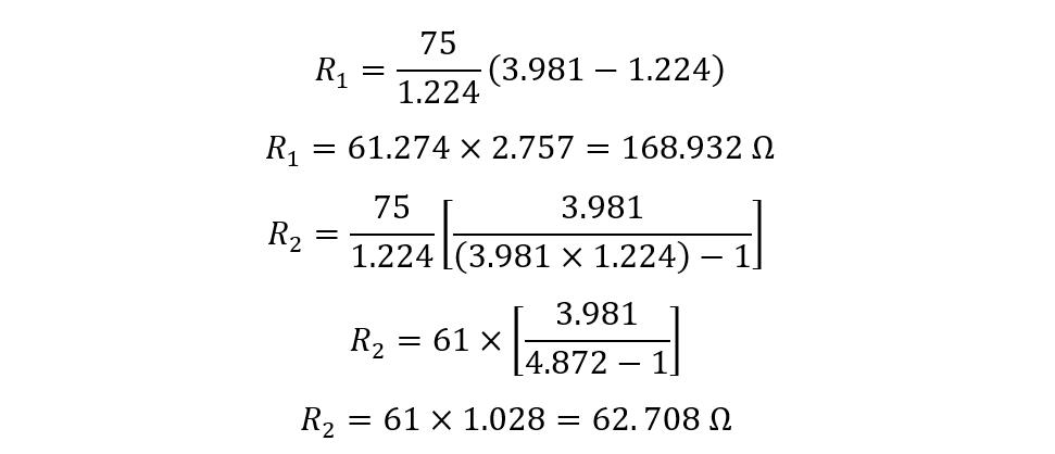
Now, just for illustration, I have calculated the values of resistance if impedance matching is in the direction of the larger impedance. The values for K and S will be the same, so just directly placing the values in the equations:
Now from the above results it is obvious that impedance matching is feasible only in the smaller impedance direction.
T-Pad Attenuator
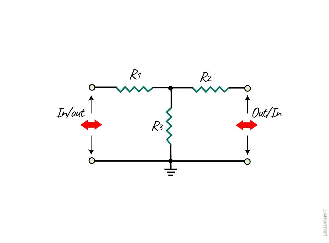
Unlike the L-Pad attenuator, this attenuator configuration is symmetrical and consists of three resistors forming a tree. The values of the resistors R1 and R2 will be equal in case of equal impedance and vice versa, below is the basic T-Pad configuration:
T-pad Attenuator with Equal Impedance
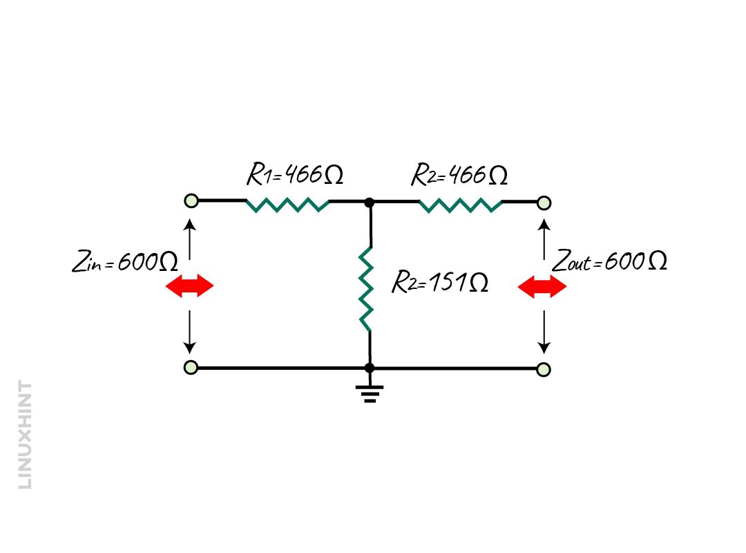
This attenuator is considered to be ideal for matching the impedance and reducing the signal levels if the source and load impedance are equal. So, to illustrate if the impedance of the source and load is 600 Ohms and the required attenuation is 18 decibels then the equations for the resistances will be:
Since the impedance for the source and load is the same, the value for the R1 and R2 will be equal. Now calculating the value for the impedance factor also referred to as voltage ratio in this case:
‘
Now find the value of K using the above equation:
So now put the impedance values to find the resistance values:
Here the R1 and R2 have the value of 466 Ohms, whereas the value of R3 is 151 Ohms:
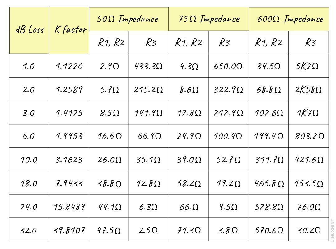
When the attenuation required increases, the series impedance of the circuit increases the series impedance of the resistors in series whereas the impedance in parallel decreases. Furthermore, here is the table below that gives the calculation of the impedance factor and attenuation on different values of impedance:
T-pad Attenuator with Unequal Impedance
When the impedance for both the source and load is not the then in that case the equations to find out the resistance values are somewhat different:
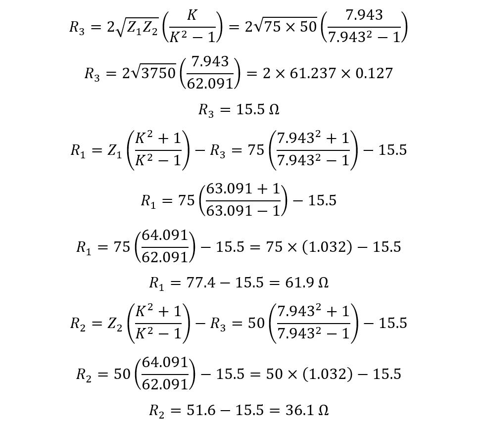
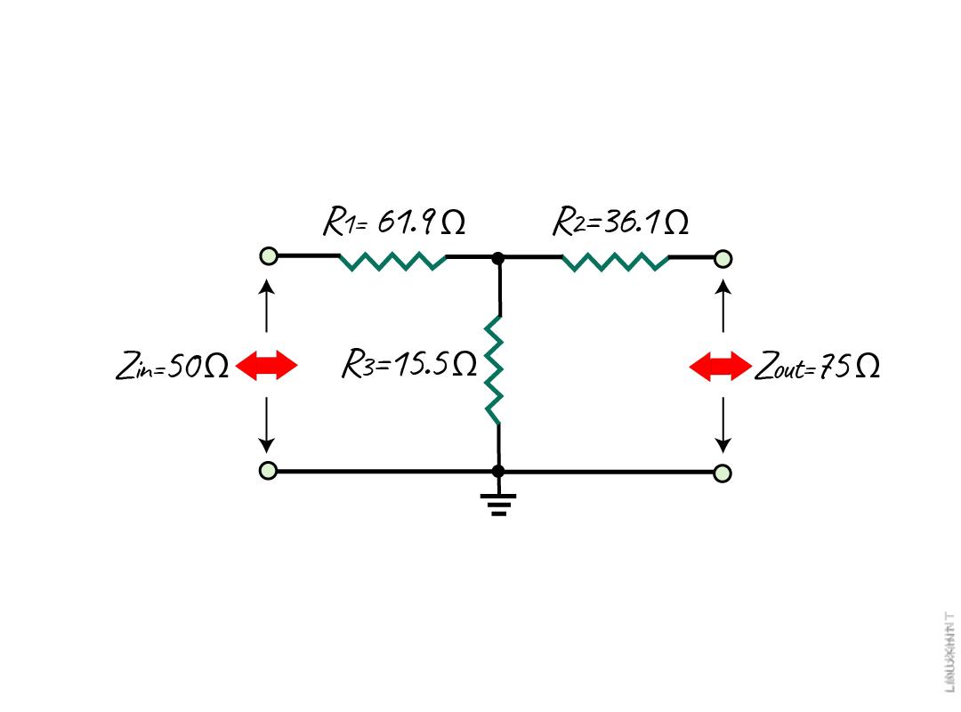
Consider a load impedance of 50 Ohms, a source impedance of 75 Ohms, and 18 decibels of reduction is required and for that, we need to calculate the resistance values using the above equations:
Now placing the values of K and finding the resistances:
The resistance value for R1 is 61.9 Ohms, for R2 it is 36.1 Ohms, and for R3 it is 15.5 Ohms, which are the preferred values.
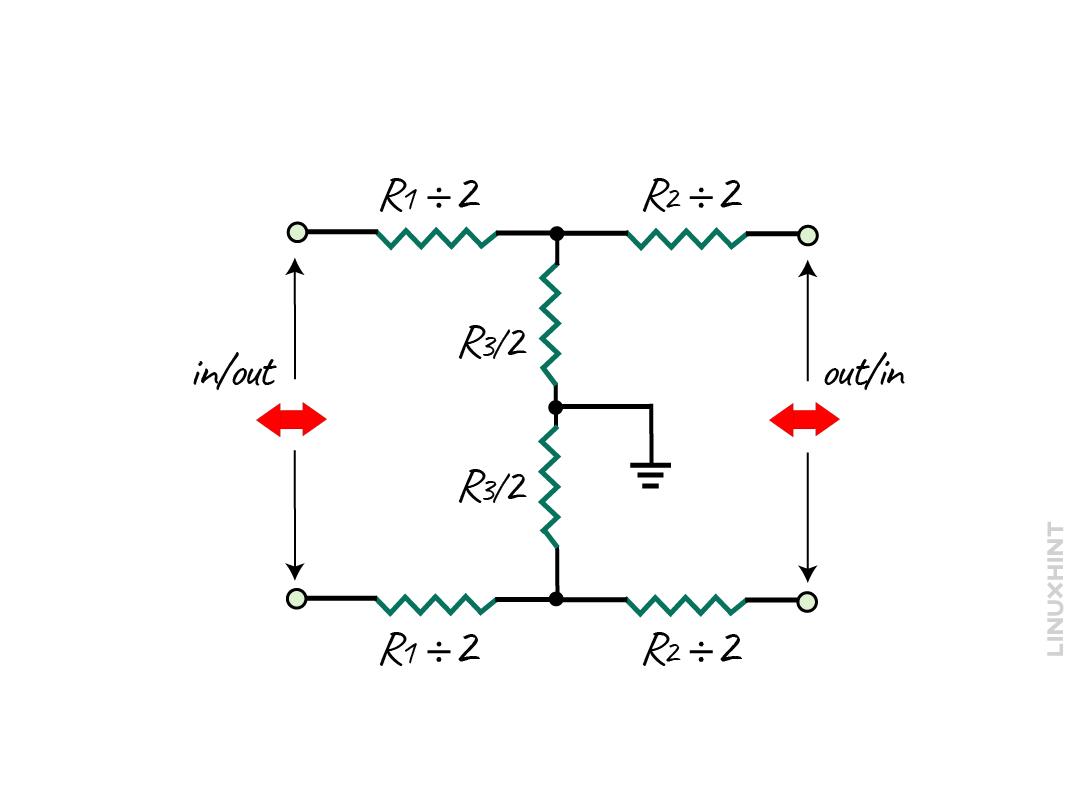
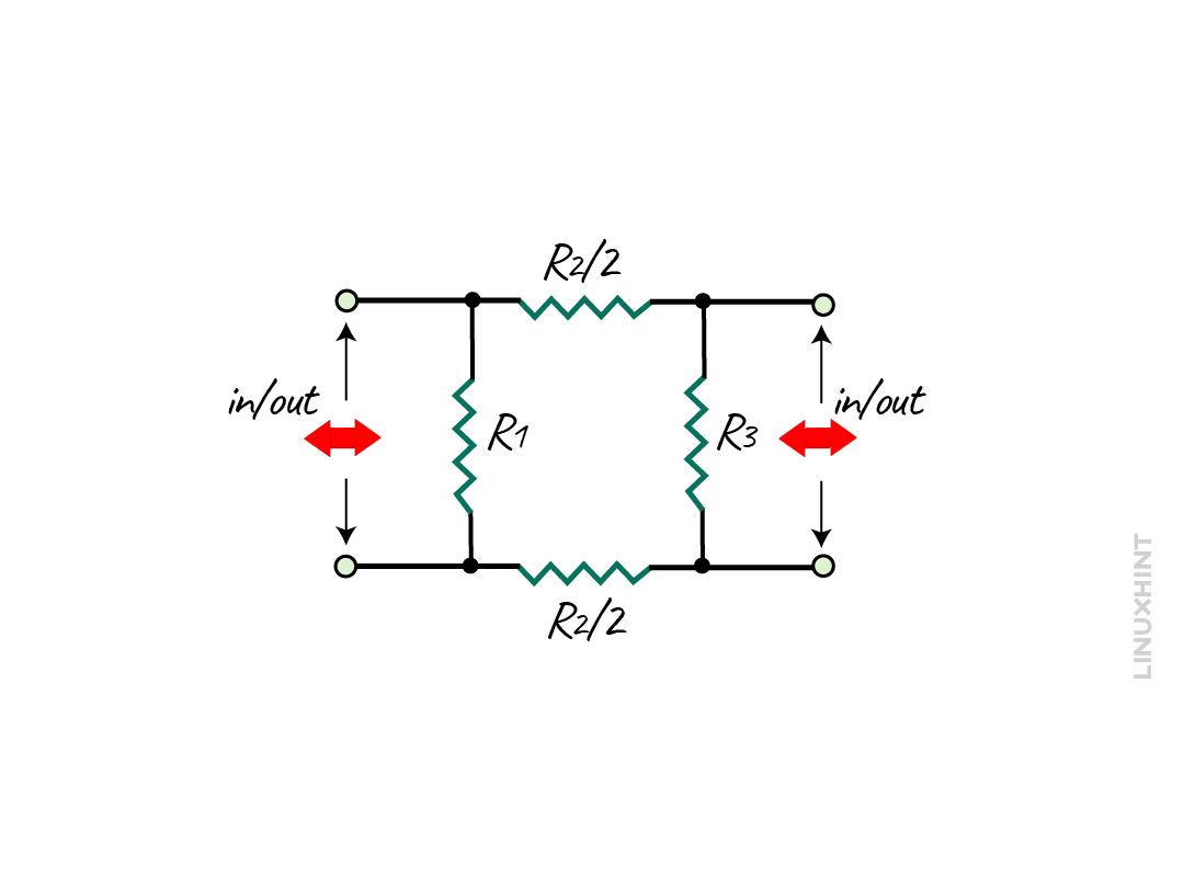
There is another configuration of the T-Pad attenuator and that i the balanced configuration having two T-pad attenuator circuits as in the image below:
So, to calculate the values for the resistance the equations are given below:
The values will be calculated in the same as done previously, but here the resistances in the series are divided in two halves. Similarly, the center of resistance in parallel is divided in half, but the total resistance remains the same.
Bridged-T Attenuator
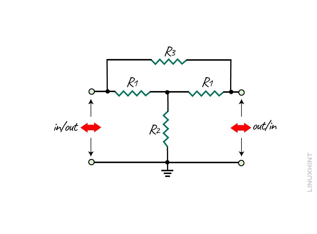
This attenuator is a modified form of a T-pad attenuator, as it has additional resistors making a bridge network. The significance of this attenuator is that it can be used to achieve the required attenuation without impedance matching. The basic bridged-T attenuator is given below:
Here, the R3 resistor creates a bridge network in this configuration, and therefore this configuration has the ability to match the transmission line characteristic impedance. The resistors R1 in series are selected to be equal to the source or load impedance, and here are equations for calculating the resistances for the bridged-T network:
Example:
Consider an audio signal having an impedance of about 20 Ohms, and the attenuation is required to reduce the signal level by 4 dB. To calculate the resistance values required using the above equations:
If the attenuation required increases, the impedance of the bridge R3 will also increase whereas the shunt resistance R2 will, tend to decrease.
Variable Bridge Attenuator
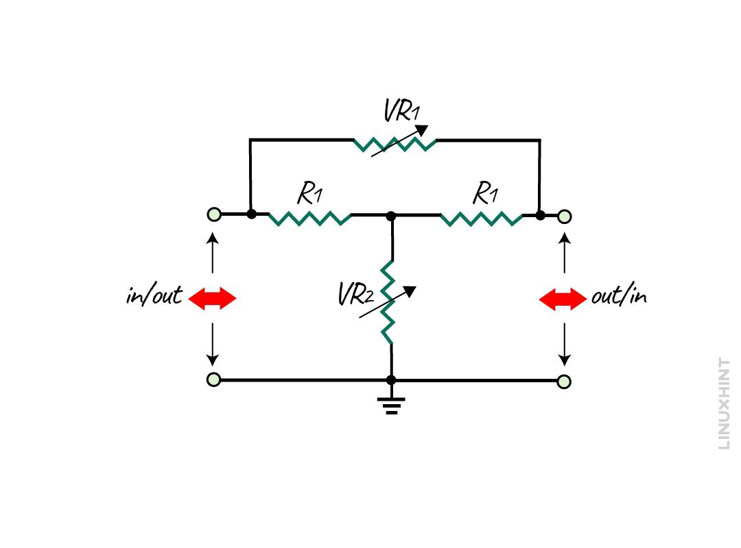
In the bridge-T network, the variable potentiometer can be used by replacing the two resistors (R2 and R3), and the basic circuit for it is given below:
Now if we implement the same example given above by changing the values of attenuation, like if the attenuation is -2 dB or -20 dB then:
When the attenuation is -20 dB, then:
Now it can be concluded that when the attenuation required is 2 decibels the maximum resistance required is 80 Ohms and when the required attenuation is 20 decibels then the maximum resistance is 180 Ohms. So, in that case the potentiometer for about 200 Ohms can be used for VR1 and VR2 respectively.
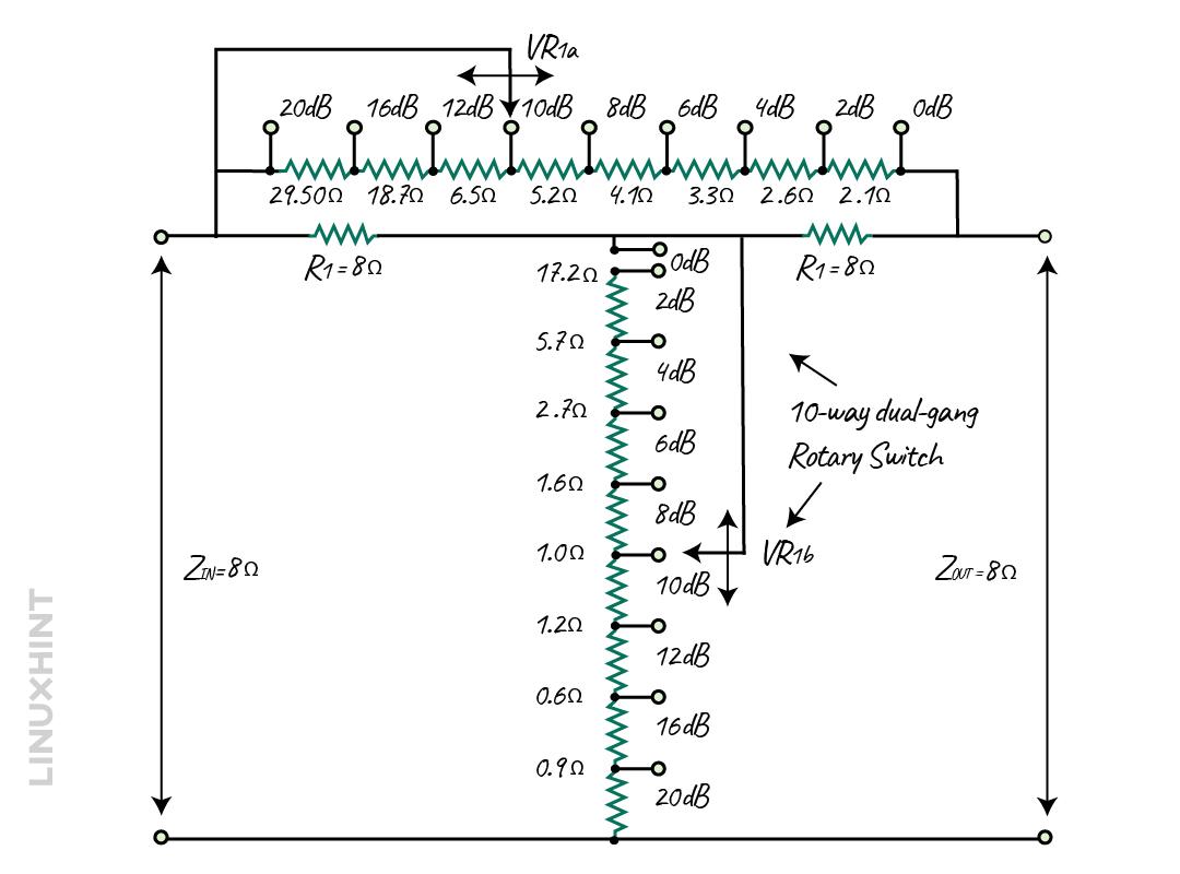
It is to be noted that in practice the single passive bridged-T network won’t go over the -30 dB as the resistance values will get too small and the noise distortion also increases. Further, we can create the stepped bridged-T attenuator by replacing the potentiometer with the fixed resistances, which can be selected through a rotary knob. If the impedance is 8 Ohms and the attenuation is in the range of -2 decibels to 20 decibels, then the stepped bridged-T attenuator circuit will be:
Now for instance, if the attenuation is 10 decibels, then the total resistance for VR1a is:
Now for VR1b the total shunt resistance will be:
Pi-pad Attenuator
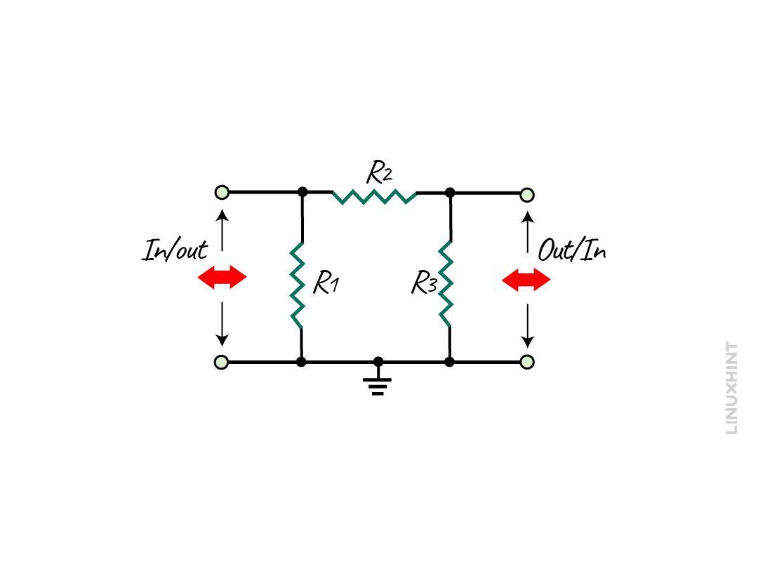
It is also a symmetrical and resistive network that can be used for impedance matching for both equal and unequal transmission lines. The configuration of the resistors in this attenuator is given below:
Normally, the resistors R1 and R3 are equal in the case of the same source and load impedance, however, they have different values in the case of unequal impedance.
Pi-pad Attenuator with Equal Impedance
The Pi-pad attenuator has three resistors that ensure the input and output impedance match to reduce the signal level to the required value. So, if the source and load impedance are equal, then the following are the equations for finding the resistances:
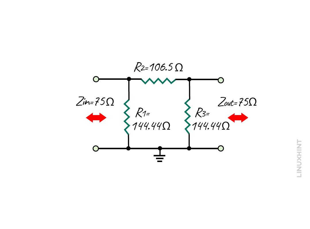
If the attenuation of -10 decibels is required and both the source and load have the same impedance of 75 Ohms, then the impedance factor and the resistances can be calculated as:
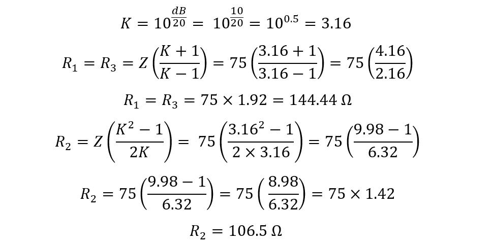
The values for the resistances R1 and R3 are 144.44 Ohms and for the R2 its 106.5 Ohms, so the circuit will be:
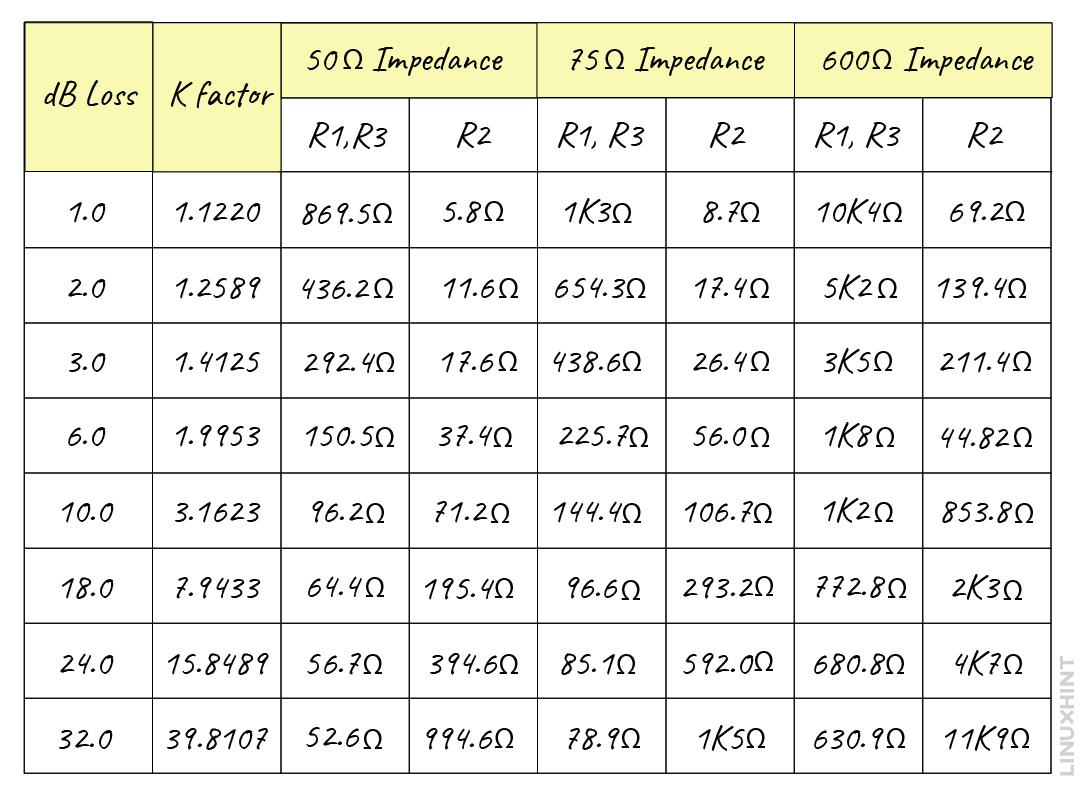
Here is the table for values of the resistances for various impedance along with the various values for impedance ratio and attenuation ratio:
It is to be noted that if the required attenuation increases then the resistance of resistor R2 increases whereas the resistance R1 and R3 decreases.
Pi-pad Attenuator with Unequal Impedance
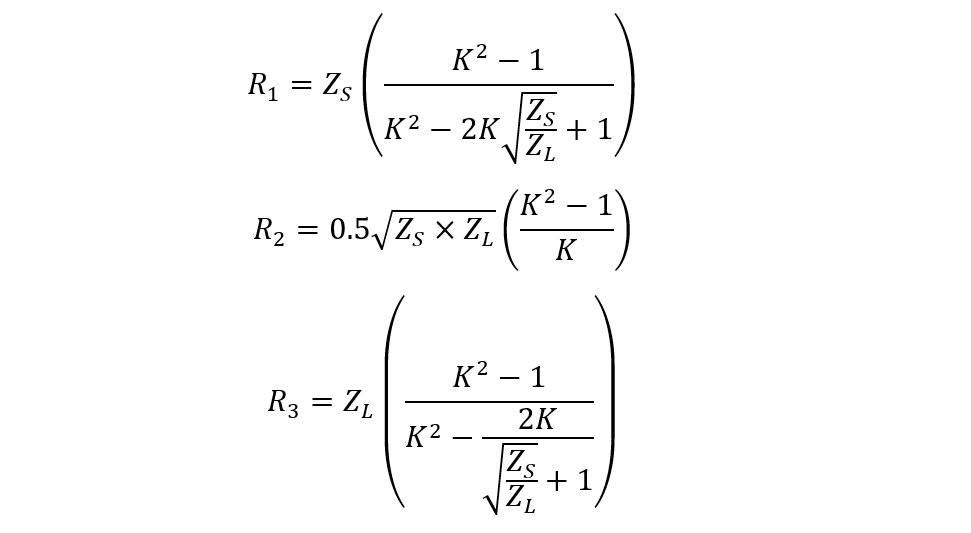
The Pi-pad attenuator can also be used to reduce the signal level for the circuit having unequal impedance. When the source and load impedance are unequal, to calculate the resistances, below are the equations:
Example:
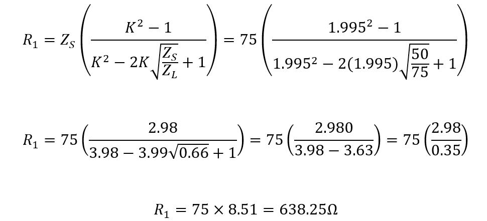
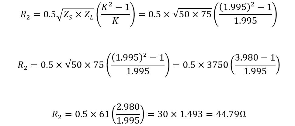
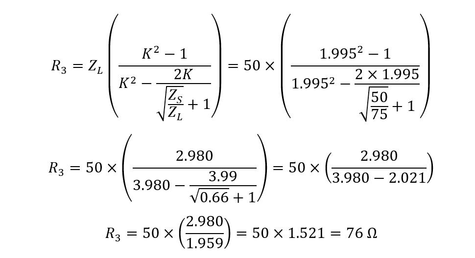
Consider a non-symmetrical Pi-pad attenuator that is required to reduce the signal levels to 6 decibels and the source impedance is 75 Ohms whereas the load impedance is 50 Ohms then first find out the impedance factor:
Now find the value for the resistance R1 using:
Now find the value for R2 resistance using:
The value for the resistance R3 will be:
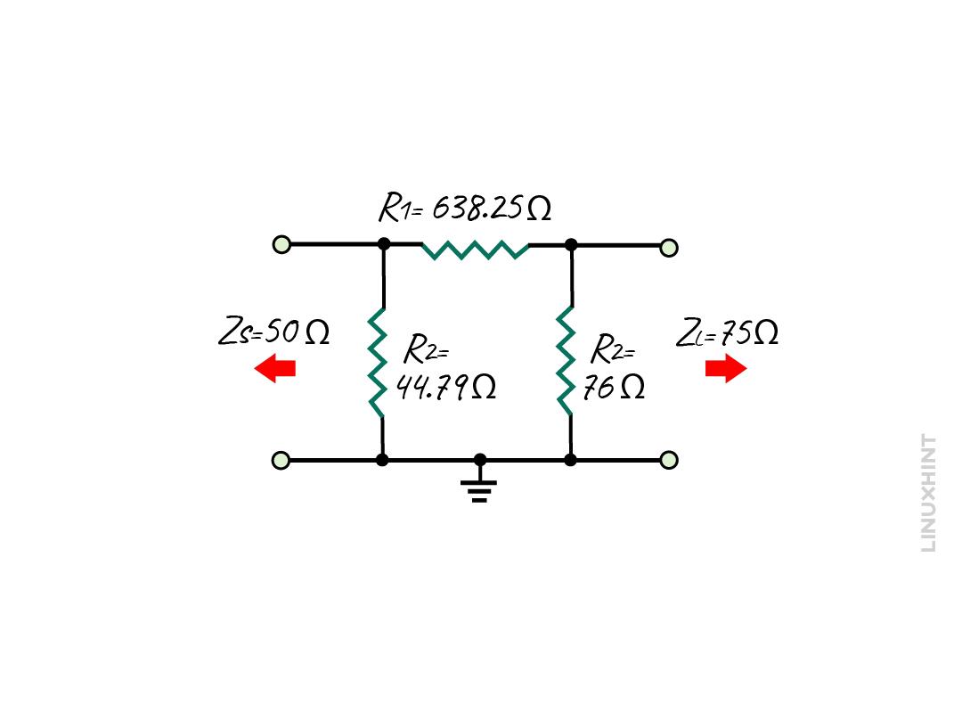
So now the circuit for Pi-pad attenuator having unequal impedance will be:
To create a balanced Pi-pad attenuator, there is one more resistance added in the circuit and the resistance of the resistor R2 is halved:
Conclusion
Attenuators are primarily used to lower the signal levels to a safe level without affecting the quality of the signal. Moreover, the attenuators are purely resistive circuits and are often referred to as passive attenuators. There are different types of attenuators which include L-pad Attenuators, T-pad attenuators, Bridged-T attenuators, and Pi-pad attenuators. Other than lowering the signal levels, attenuators are used for impedance matching, stabilizing amplifier output, and reducing voltage standing wave ratio.


