Multivibrators usually have two different operational states. These circuits continue to switch between the two states as both states are stable. During the continuous alterations, multivibrators produce square waves at output. This article describes astable multivibrators in detail.
Astable Multivibrator
Astable multivibrators are free running oscillators due to their ability to produce square waves-based output without any external inputs. There are no stable states in an astable multivibrator as the Multivibrator simply switches states between two states automatically after a certain amount of time. This time of switching states is set by the RC time constants.
Construction
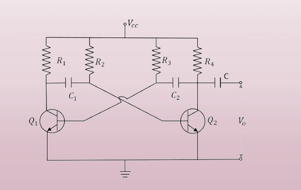
The feedback connection between the two transistors Q1 and Q2 is established for multivibrator circuit configuration as shown below. Through the capacitor C1, the base of transistor Q2 is linked to the collector of transistor Q1, and similarly for the transistor Q1. Both transistors have a ground reference connection for their emitters as shown in the circuit below. The collector load resistors R1 and R4 and the two biasing resistors R2 and R3 share the same value. The values of capacitor C1 and capacitor C2 are identical.
Working Principle
The transistors’ collector current is given by:

Q1 conducts as a result of an increase in collector current. Through C1, the base of Q2 receives the application of Q1‘s collector. This connection enables Q2‘s base to receive an enhanced negative voltage from Q1‘s collector, which reduces Q2‘s collector current. The collector current of transistor Q2 continues to fall gradually. When this current is delivered to the base of Q1, it makes Q1 more negatively biased, and as a result of the cumulative effects, Q1 becomes saturated and Q2 cuts off. Therefore, Q1‘s output voltage will be VCE (sat), while Q2‘s output voltage will be VCC.
When the voltage across the capacitor C1 hits 0.7 volts, the transistor Q2 is sufficiently saturated to switch on when the capacitor C1 charges through R1. The base of Q2 becomes saturated when this voltage is applied, reducing the collector current. The Q1 reverse bias potential is produced by delivering this drop in voltage at point B to the base of the transistor Q1 through capacitor C2. These operations cause the transistors Q1 and Q2 to become saturated and switched off, respectively. When the voltage across this capacitor C2 reaches 0.7 volts, the transistor Q1 is turned on till its saturation.
Thus, the output voltage is created by the transistors Q1 and Q2 flipping in alternating fashion. The values of the biasing resistors, capacitors, or RC values determine how long these ON/OFF switching states last.
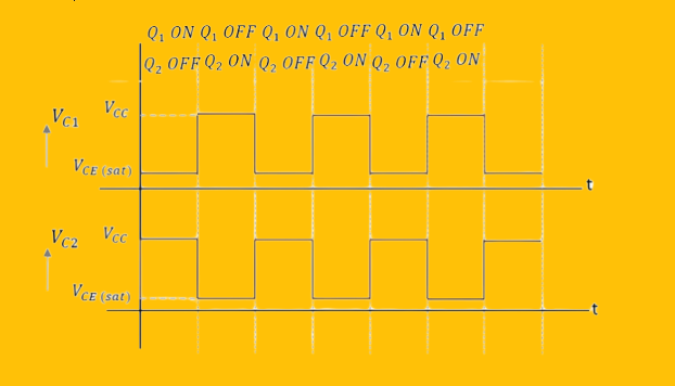
Output Voltage Waveform
The output is a square waveform pattern with both VCCs peak amplitudes since both transistors run alternately.
Frequency of Oscillations
Transistor Q1‘s ON or OFF time is provided by:

The ON or OFF time of transistor Q2 is provided by:

Consequently, the square wave’s overall period can be evaluated as:

The frequency of a square wave at R1 = R2 = R and C1 = C2 = C

Conclusion
Astable oscillators do not require external inputs to generate oscillations. That is why they are called free running oscillators. They can produce continuous square waves outputs and width of these square waves can be controlled by choosing different resistor and capacitor values in its construction.