Introduction to RGB LED
An RGB LED is a type of LED that is capable of emitting light in various colors by mixing the intensities of the red, green, and blue wavelengths. PWM (Pulse Width Modulation) signal can be used to create multiple colors by adjusting the duty cycle of the PWM signal generated for the three primary colors.
RGB LED Module
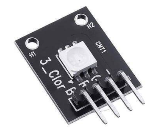
Different RGB LED modules are available like HW-478, KY-016, and KY-009. We will use the HW-478 RGB module. Working principles of all these modules are the same.
HW-478 RGB module has following specification:
| Specifications | Value |
|---|---|
| Operating Voltage | 5V max |
| Red | 1.8V – 2.4V |
| Green | 2.8V – 3.6V |
| Blue | 2.8V – 3.6V |
| Forward Current | 20mA – 30mA |
| Operating Temperature | -25°C to 85°C [-13°F – 185°F] |
| Board Dimensions | 18.5mm x 15mm [0.728in x 0.591in] |
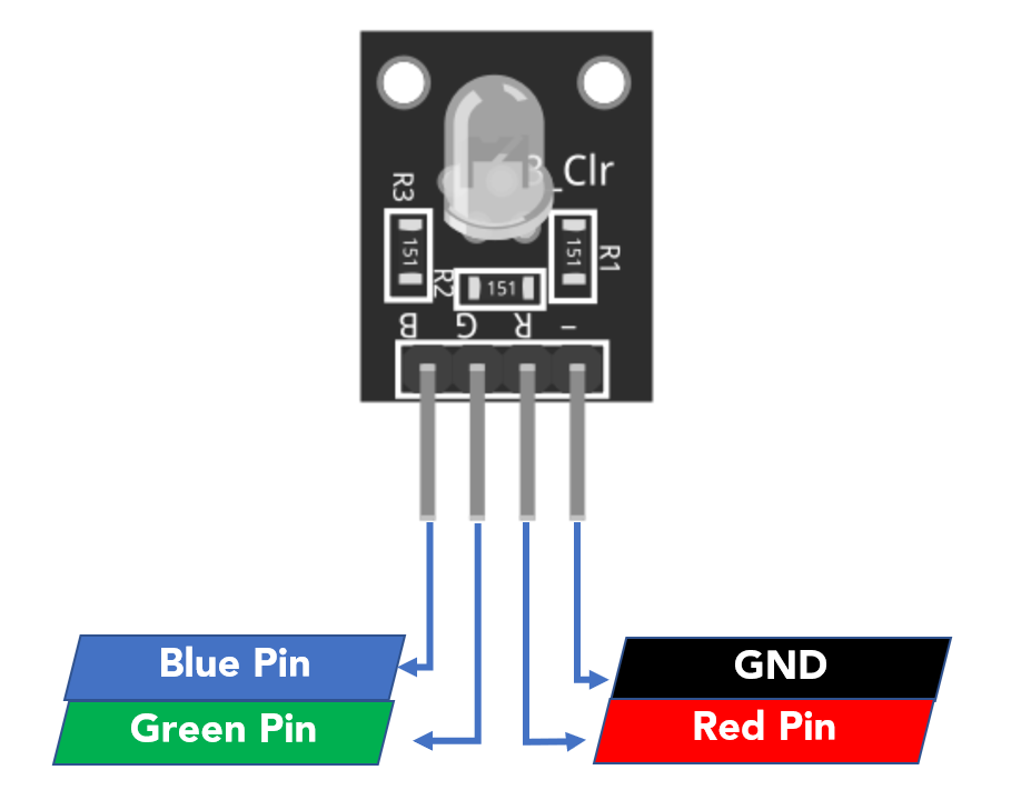
RGB LED HW-478 Pinout
Following are the 4 pins in RGB module:
Working of RGB LED
An RGB LED is a type of LED that can emit three different colors of light: red, green, and blue. The working principle of an RGB LED with Arduino involves using pulse width modulation (PWM) to control the intensity of each color.
By adjusting the duty cycle of the PWM signal, the Arduino can change the amount of current flowing through each LED, causing the LED to emit a different color of light. For example, if the duty cycle of the red LED is set to a high value, the LED will emit a bright red light. If the duty cycle of the green LED is set to a low value, the LED will emit a dim green light. By combining the intensities of the three colors, the Arduino can create a wide range of different colors.
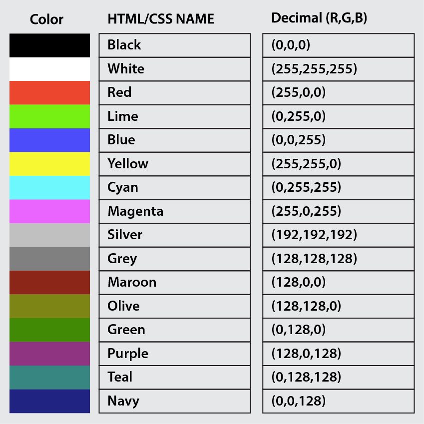
The Arduino PWM duty cycle value varies between 0 and 255. By assigning a PWM value to any color we can either set it as full bright or turn it off completely. 0 corresponds to LED off and 255 corresponds to full brightness.
How to Display Multiple Colors in RGB LED
To display multiple colors, we have to define the PWM values for three primary colors (RGB). To display any color first we have to find the color code. Following is the color code list for some of the main colors:
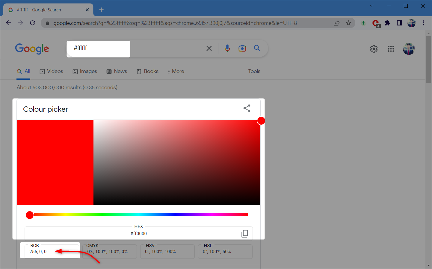
To find the color code one can use the Google Color Picker. Using this tool, we can also get the HEX RGB value for the respective color.
Now we will move towards the interfacing of RGB LED with Arduino Nano.
Interfacing RGB LED with Arduino Nano
To interface RGB LED module with Arduino Nano following components are needed:
- Arduino Nano
- 3×220 Ohm (Ω) Resistor
- RGB LED Module HW-478
- Jumper Wires
- Breadboard
- Arduino IDE
Schematic
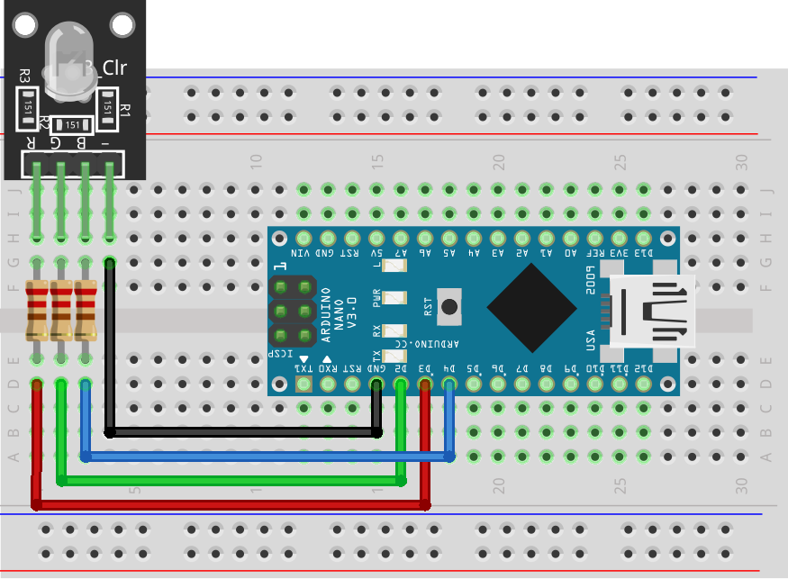
The given image represents the schematic of Arduino Nano with RGB LED.
Hardware
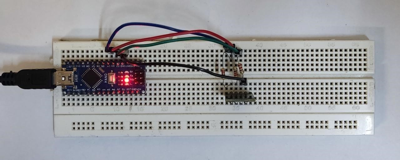
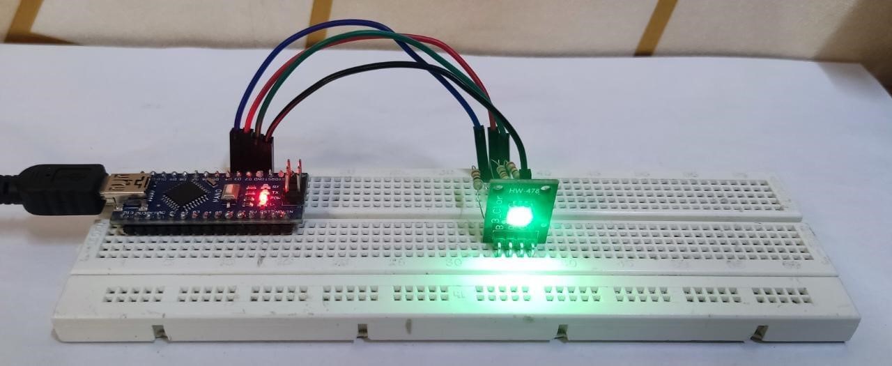
Following hardware is designed on a breadboard. A resistor is connected to each pin for protection of the LED circuit.
Code
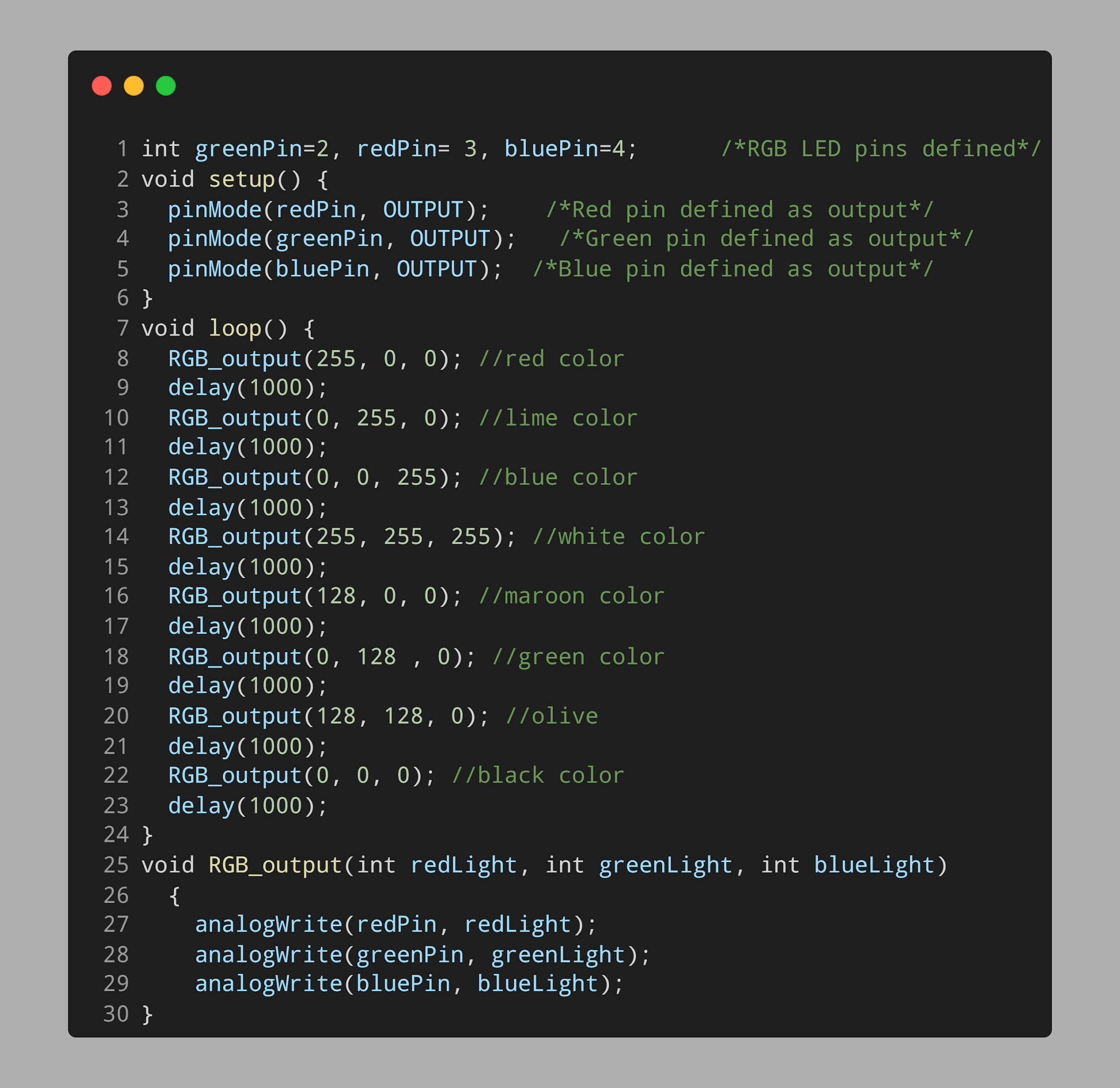
Open Arduino integrated environment and upload given code to Arduino Nano board:
void setup() {
pinMode(redPin, OUTPUT); /*Red pin defined as output*/
pinMode(greenPin, OUTPUT); /*Green pin defined as output*/
pinMode(bluePin, OUTPUT); /*Blue pin defined as output*/
}
void loop() {
RGB_output(255, 0, 0); //Set RGB color to Red
delay(1000);
RGB_output(0, 255, 0); //Set RGB color to lime
delay(1000);
RGB_output(0, 0, 255); //Set RGB color to blue
delay(1000);
RGB_output(255, 255, 255); //Set RGB color to white
delay(1000);
RGB_output(128, 0, 0); //Set RGB color to maroon
delay(1000);
RGB_output(0, 128 , 0); //Set RGB color to green
delay(1000);
RGB_output(128, 128, 0); //Set RGB color to olive
delay(1000);
RGB_output(0, 0, 0); //Set RGB color to black
delay(1000);
}
void RGB_output(int redLight, int greenLight, int blueLight)
{
analogWrite(redPin, redLight); //write analog values to RGB
analogWrite(greenPin, greenLight);
analogWrite(bluePin, blueLight);
}
First RGB pins are initialized for sending the PWM signal. Digital pin 2 is initialized for green color and similarly D2 and D3 are initialized for red and blue color.
In the loop part of the code different colors are defined using their HEX RGB value. Each of these values describes a PWM signal.
Next in the void RGB_output() function we passed 3 integers that set different colors on RGB light. For example, for white color we have to pass 255 in each of three parameters. Every primary color red, blue and green will be bright to its full value as a result giving us white color in output.
Output
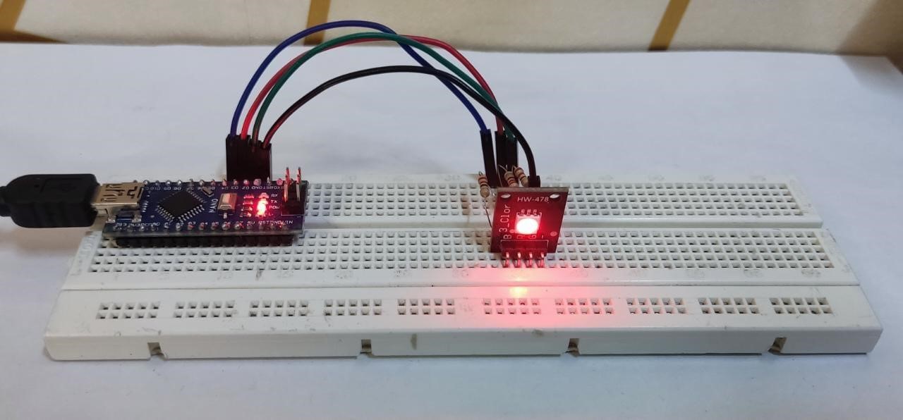
After uploading code, we will see different colors on the RGB LED. Below image shows us the RED color.
This image represents the color green.
We have interfaced the RGB LED module with the Arduino Nano.
Conclusion
Arduino Nano is a compact board that can be integrated with different sensors. Here we have used an RGB LED with Arduino Nano and programmed it to display multiple colors using a PWM signal from an Arduino Nano digital pin. For more description of RGB read article.

