This article covers:
- What Is I2C Communication in Arduino
- I2C Pins in Arduino Uno
- I2C Pins in Arduino Mega
- I2C Pins in Arduino Nano
- Brief Comparison of Arduino I2C Pins
- Connecting Two Arduino Board Using I2C As Master and Slave
- Conclusion
What Is I2C Communication in Arduino
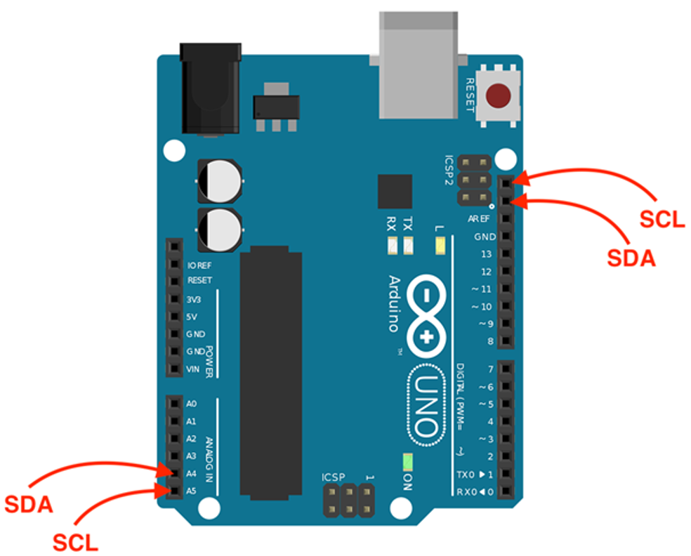
I2C communication pins refer to the specific pin connections on an Arduino board that are used to communicate with I2C devices. On most Arduino boards, the I2C communication pins are located on the A4 and A5 pins, and are labeled SDA (for data) and SCL (for clock) respectively.
Some main highlights of I2C communication include:
Multi-Master and Multi-Slave capability: I2C supports multiple master devices and multiple slave devices on a single bus, allowing for communication between multiple devices at the same time.
Low Pin Count: I2C uses only two lines, SDA and SCL, for communication, which reduces the number of required connections and simplifies wiring.
Addressable devices: Each I2C device on the bus has a unique address, allowing for easy identification and communication with specific devices.
High Speed: The I2C specification supports data transfer rates of up to 3.4 Mbps, making it suitable for high-speed data transfer applications.
Power Saving: I2C allows for low-power communication between devices by allowing devices to be put into low power modes when not communicating and wake up on request.
I2C Pins in Arduino Uno
In I2C communication, two lines are utilized:
- Data line (SDA): Data line for exchanging data between Master and Slave devices.
- Clock line (SCL): Clock line for synchronizing the I2C communication between devices.
The Master device is responsible for controlling the clock line and initiating the communication, while the Slave devices are responsible for responding to the master’s requests.
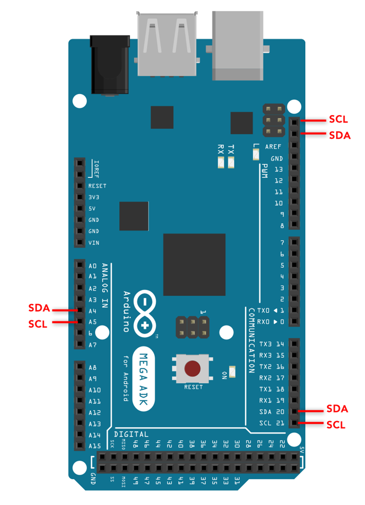
I2C Pins in Arduino Mega
The Arduino Mega has multiple I2C communication pins. These pins are:
- SDA – A4 & 20
- SCL – A5 & 21
These pins can be used to connect I2C devices, such as sensors or other microcontrollers.
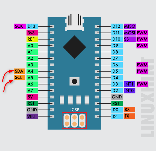
I2C Pins in Arduino Nano
The I2C pins on the Arduino Nano are A4 (SDA) and A5 (SCL), these pins can be used to communicate with I2C devices such as sensors, LCD displays, and other microcontrollers. To use these pins, you will need to use the Wire library, which is built into the Arduino IDE:
It is important to note that the I2C pins on the Arduino Nano can also be used as standard digital I/O pins if they are not being used for I2C communication. However, it is important to make sure that the I2C communication is disabled or stopped before using these pins as digital I/O, as it can cause conflicts and errors.
Brief Comparison of Arduino I2C Pins
Here is a list of some popular Arduino boards and their corresponding I2C pins:
| Board | I2C Pins |
|---|---|
| Arduino Nano | SDA-A4 | SCL-A5 |
| Arduino Mega | SDA-A4 | SCL-A5 and SDA-20 | SCL-21 |
| Arduino Leonardo | SDA-A4 | SCL-A5 |
| Arduino Uno | SDA-A4 | SCL-A5 |
| Arduino Micro | SDA-02 | SCL-03* |
| Arduino Leonardo | SDA-02 | SCL-03 |
| Arduino Micro | SDA-02 | SCL-03 |
| Arduino Pro Mini | SDA-A4 | SCL-A5 |
| Arduino Due | SDA-20 | SCL-21 |
| Arduino 101 | SDA-20 | SCL-21 |
*I2C Pins may vary depending upon which board version you are using kindly see respective datasheet for more details.
Please note that some of the boards may have more than one SDA, SCL pins, in such case you may use any of them as per your requirement and availability. It’s also good to refer to the official documentation of the board you are using, to confirm the I2C pinout.
Connecting Two Arduino Board Using I2C As Master and Slave
To establish I2C communication between two Arduino boards, the SDA and SCL pins of both boards must be connected and share a common ground. The communication can be achieved by using the inbuilt Wire library in Arduino which contains functions for configuring and communicating on the I2C bus.
Schematic
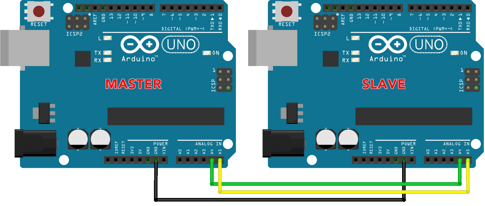
Below image shows two Arduino Uno boards connected in Master-Slave configuration:
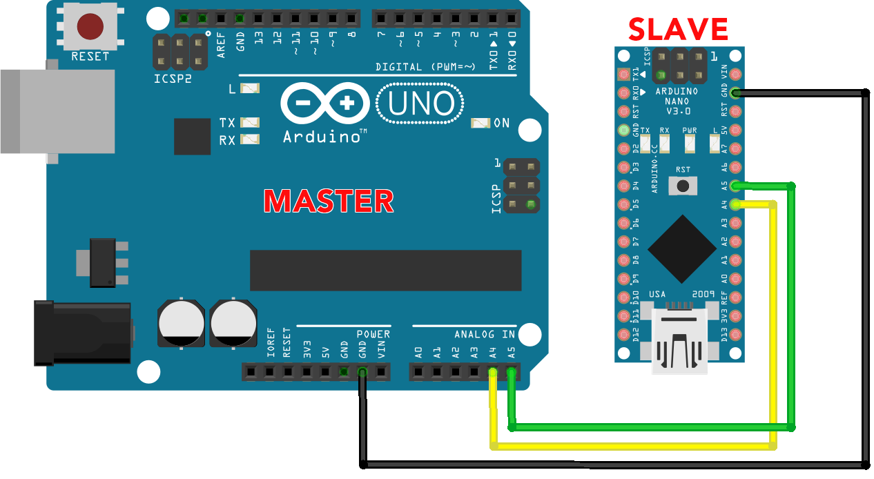
To connect Arduino Uno with Arduino Nano using I2C master slave protocol follow the below configuration:
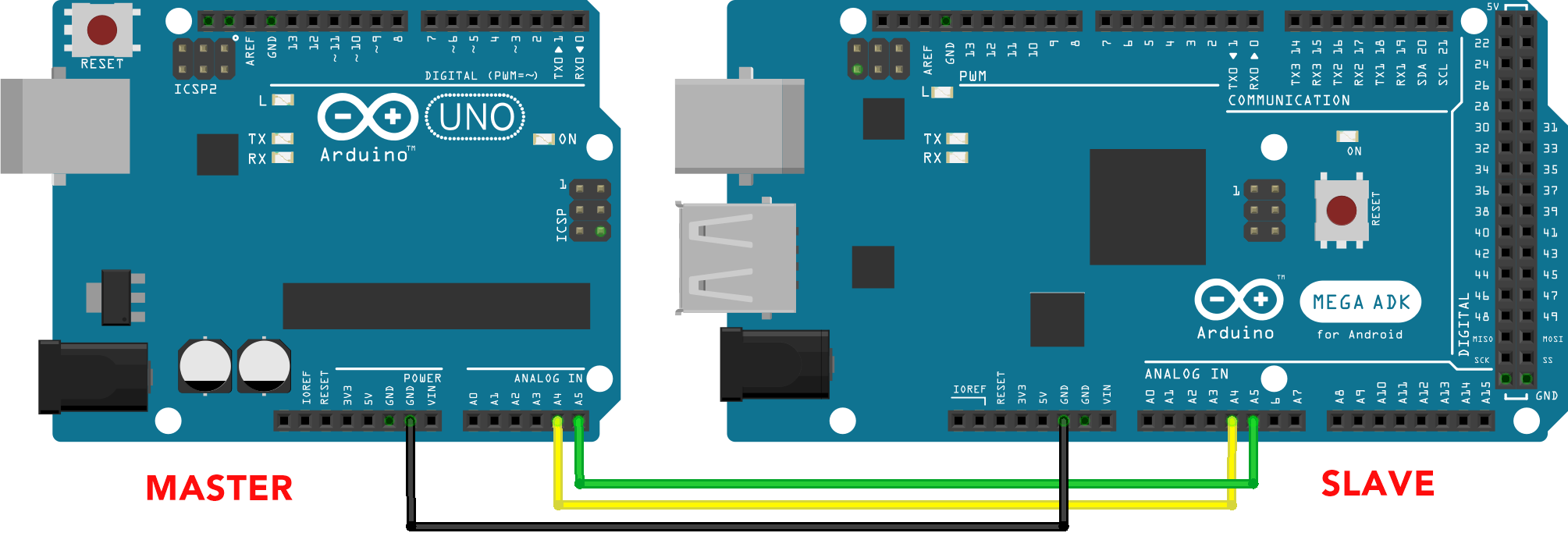
Arduino Mega connection with Arduino Uno using I2C:
Conclusion
Arduino boards can be configured to communicate with one another using I2C by connecting the SDA and SCL pins and configuring the boards as Master and Slave using the Wire library in Arduino. This allows for efficient and easy communication between multiple devices in any Arduino based project.